MEA2100-System Manual
Information in this document is subject to change without notice. No part of this document may be reproduced or transmitted without the express written permission of Multi Channel Systems MCS GmbH. While every precaution has been taken in the preparation of this document, the publisher and the author assume no responsibility for errors or omissions, or for damages resulting from the use of information contained in this document or from the use of programs and source code that may accompany it.
Table of Contents 1 1.1 1.2 Introduction About this Manual Welcome to the MEA2100-System 1 1 1 2 2.1 2.2 2.3 Important Safety Advice Important Safety Advice Guarantee and Liability Operator's Obligations 3 3 4 4 3 3.1 3.2 3.3 3.4 3.5 Software Setting up MC_Rack System Requirements First Use of MC_Rack Setting up the Internal Stimulus Generator Setting up LTP-Director Software 3.5.1 System requirements 3.5.2 Recommended operating system settings 3.5.3 Installing the LTP-Director Software 3.5.
MEA2100-System Manual iv 6 6.1 6.2 6.3 6.4 6.5 6.6 6.7 Troubleshooting About Troubleshooting No Computer Connection / No Recording Possible Triggering / Digital Input does not Work Noise on Single Electrodes MEA is defective Overall Noise / Unsteady Baseline Missing Spikes or Strange Signal Behavior 45 45 45 46 46 47 47 48 7 7.1 7.2 7.3 7.4 7.5 7.6 7.
1 Introduction 1.1 About this Manual It is assumed that you already have a basic understanding of technical and software terms. No special skills are required to read this manual. If you are using the device for the first time, please read the Important Safety Advice before installing the hardware and software, where you will find important information about the installation and first steps. The device and the software are part of an ongoing developmental process.
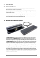
MEA2100-System Manual Data is recorded, stimulated, analyzed, graphed and reviewed with the powerful and easy-to-use MC_Rack program from Multi Channel Systems MCS GmbH. The control functions of the internal stimulator are also integrated into MC_Rack. The MC_Rack data format can be converted in other standard formats with the software MC_DataTool. The Headstage of the MEA2100-System At the moment five different types of headstages are available for the MEA2100-System.
2 Important Safety Advice 2.1 Important Safety Advice Warning: Make sure to read the following advice prior to installation or use of the device and the software. If you do not fulfill all requirements stated below, this may lead to malfunctions or breakage of connected hardware, or even fatal injuries. Warning: Always obey the rules of local regulations and laws. Only qualified personnel should be allowed to perform laboratory work.
MEA2100-System Manual 2.2 Guarantee and Liability The General conditions of sale and delivery of Multi Channel Systems MCS GmbH always apply. The operator will receive these no later than on conclusion of the contract. Multi Channel Systems MCS GmbH makes no guarantee as to the accuracy of any and all tests and data generated by the use of the device or the software. It is up to the user to use good laboratory practice to establish the validity of his / her findings.
3 Software 3.1 Setting up MC_Rack Warning: The operating system settings of the data acquisition computer were preconfigured by MCS and should not be changed by the user. Changing these settings can lead to program instabilities and data loss. Important: The driver of the MEA2100-System is automatically installed together with the MC_Rack program. Please install MC_Rack before connecting the MEA2100-System to a data acquisition computer.
MEA2100-System Manual Connecting the MEA2100-System After MC_Rack has been installed on the computer and the MEA2100 device is connected for the first time, the operating system needs to load the driver once. After this procedure, the MEA2100-System will be automatically recognized by the operating system. 1. Connect the MEA2100-System to the USB port of the data acquisition computer. Please make sure the device has power, that is, the power LED is lighting. Switch the computer on. 2.
Software 3.2 System Requirements One of the following Microsoft Windows ® operating systems is required: Windows 8.1, Windows 7 (32 or 64 bit), VISTA or XP, English and German versions supported. Other language versions may lead to software errors. If no MEA2100-System is present, MC_Rack opens in a simulation mode. A computer with low performance may lead to performance limits more often; therefore, MCS recommends an up-to-date computer optionally with a separate hard disk.
MEA2100-System Manual 3.3 First Use of MC_Rack Data Source Setup Every MEA of the MEA2100-System can be operated completely independently by one instance of MC_Rack. To be able to open more than one instance of MC_Rack, please first open the "Advanced Configuration" dialog in the "Edit" menu.
Software Select “USB” and MEA2100 (S/N: XXXXX-A) as Data Source. Select “Configuration” in the “Source Layout”. Please select the type of the connected headstage in the "Amp" drop down menu. If a MEA2100-HS2x60 is connected you have additionally to select the "Block" in the right drop down menu of “Virtual Device Configuration”. For the first instance of MC_Rack, select Block 1 (Channel 1…64) and for the second instance Block 2 (Channel 65…128).
MEA2100-System Manual Hardware Settings for the MEA2100-System in the Data Source When using the MEA2100-System, the “Hardware” tab of the MC_Rack software is modified. Please see also chapter “Defining a Data Source”. In the "Hardware" tab of the Data Source, the gain setting must be adjusted to ensure a correct scaling of the data in MC_Rack.
Software 3.4 Setting up the Internal Stimulus Generator The headstage of the MEA2100-System is equipped with an integrated 3-channel stimulus generator. The three stimulation channels operate independently. Even when using multiple instances of MC_Rack, each instance is completely independent and each instance has three stimulus channels available for the electrodes which are controlled by that instance.
MEA2100-System Manual Click “Stimulus 1” tab page, for example. Defining the stimulation pulse In "Output Mode" you can choose whether you want to stimulate in voltage or current mode. To set up the stimulus pulse or pulse train, please use the eight provided up down boxes. The individual stimulation pulse is defined in the "Pulse" window. Set up a monophasic pulse by selecting the voltage / current in mV/μA and the duration time T1 in μs.
Software If the “Continuous Mode” is activated, the paradigm will be repeated indefinitely, till manually stopped. Please note that stimulation does not stop when MC_Rack is stopped. Importing a stimulation file created with MC_Stimulus II To generate more complex stimulation patterns it is possible to import a stimulation file setup with the MC_Stimulus II software as ASCII data. Please read the respective stimulus generator STG manual for detailed information about creating a stimulus file.
MEA2100-System Manual Starting and stopping the stimulation In the "Trigger" drop down menu it is possible to choose different types of triggers to start the stimulation. The LED next to the Start / Stop button indicates the status of stimulation; the LED turns orange when the stimulation is running, the LED turns grey when the stimulation is stopped.
Software Selection of stimulation electrodes Click the “Channels” tab to assign the programmed stimulation patterns to individual electrodes, and to activate the blanking circuit BC, and to operate the “List Mode”. To apply the stimulation pattern of a specific stimulation channel (Stim. 1, 2 or 3) to one or more electrodes, select the desired stimulation channel (Stim. 1 to 3) and click the electrodes you want to apply this paradigm to.
MEA2100-System Manual Blanking A blanking signal transiently switches off the input stage of the amplifier during the stimulus, thus avoiding stimulus artifacts on non-stimulating electrodes. Amplifier saturation is effectively prevented and the recovery time is greatly reduced. During the blanking period, a flat line is displayed. This blanking period extends a few hundred microseconds before and after the actual stimulus, currently 600 μs, but might be subject to change.
Software List Mode Clicking the button List Mode opens an additional window: List of Stimulation Patterns. In List Mode it is possible to generate and download a list of up to 256 user defined stimulation patterns, which will then be applied automatically one after the other. When the List Mode is activated, the three stimulator units are coupled to a single starting trigger. The starting trigger is set in the tab of the first stimulator unit, Stimulus 1.
MEA2100-System Manual Click the button “List Mode”. There are two windows in the “List of Stimulus Pattern”. The small window on the right side is for typing in a name for a pattern. In the window on the left side the list of stimulation pattern will be displayed and arranged. When opening the “List Mode” for the first time, the term “New” appears and the current stimulation pattern is the first stimulation pattern in the list.
Software Use of the Digital Channel in the MEA2100-System In contrast to the other MEA- and ME-Systems from Multi Channel Systems, the 16 input bits of the digital channel are not all accessible for external trigger signals, but are mostly used for internal communication between the different components of the MEA2100-System. Only the first four bits are connected to the physical DigIn connectors on the front side of the MEA2100 interface board. Most bits are permanently assigned to certain functions.
MEA2100-System Manual To monitor the digital data stream you can use the “Digital Display” tool. If a MEA2100 device is connected, the input bits will be labeled according to their function in the digital display. If a MEA2100-32 device is connected, the “Real-time feedback” is not available, respectively the real-time feedback specification 1 to 8 are not available. Therefore the input bits are used for the digital inputs, bit 0 to bit 12 to digIn 1 to 13.
Software To record the digital data stream in the data file, please enable the respective check box in the “Channels" tab of the Recorder tool. . Triggering on Stimulation Pulses from Internal STGs It is possible to trigger on stimulation pulses from any of the three internal stimulus generators. The three internal STG units send a trigger signals with each stimulation pulse on bits 4, 5 and 6 of the digital channel, Stimulus 1 on bit 4, Stimulus 2 on bit 5 and Stimulus 3 on bit 6.
MEA2100-System Manual Real-time Feedback with MEA2100-System Important: The real-time feedback is not available in MEA2100-32- and MEA2100-Lite-Systems! The interface board of the MEA2100-System is equipped with a high-capacity digital signal processor DSP. By moving the detection and analysis of signals from the data acquisition computer to the digital signal processor inside the interface, it is possible to run online filtering, analysis and feedback stimulation in real-time.
Software 3.5 Setting up LTP-Director Software When operating a MEA2100-System, you can connect the devices to any data acquisition computer. Make sure that the recommended system requirements are fulfilled. The data acquisition computer from Multi Channel Systems MCS GmbH together with the MEA2100-System comes preinstalled and preconfigured for a flawless operation.
MEA2100-System Manual 3.5.3 Installing the LTP-Director Software Important: Please make sure that you have full control over your computer as an administrator for software installation. Otherwise, it is possible that the installed software does not work properly. For using the software it is not necessary to have administrator control. 1. Double-click the Setup.exe on the installation volume. The installation assistant will show up and guide you through the installation procedure. 2.
Software 3.6 Setting up Cardio2D Software When operating a MEA2100-System, you can connect the devices to any data acquisition computer. Make sure that the recommended system requirements are fulfilled. The data acquisition computer from Multi Channel Systems MCS GmbH together with the MEA2100-System comes preinstalled and preconfigured for a flawless operation.
MEA2100-System Manual 3.6.1 Installing the Cardio2D Software Make sure to have a valid license for the Cardio2D software! Please ask license@multichannelsystems.com. You do not need a license for the Cardio2D software if you like to test the software for getting an idea of how it works and what is possible. You can test all functions, run the viability test to see your data, but you are not able to start an experiment. Please contact license@multichannelsystems.com to receive a valid license key.
4 Hardware 4.1 Hardware Configuration The MEA2100-System is a flexible system, which can be used in different configurations. At the moment five types of headstages are available for the MEA2100-System, which can be connected to the interface board once or twice: A headstage for one MEA with 32 (MEA2100-HS32), with 60 (MEA2100-HS60), or with 120 electrodes (MEA2100-HS120). Respectively headstages for two MEAs are available, for two MEAs with 32 or 60 electrodes each (MEA2100-HS2x32 or MEA2100-HS2x60).
MEA2100-System Manual 4.2 MEA2100 Interface Board The MEA2100-System consists of two main devices: The Interface board with integrated signal processor, and a headstage equipped with amplifiers, an integrated stimulator and analog-todigital converter ADC. Front Panel Two Status LEDs The status LEDs indicate the link status of headstage 1 and / or headstage 2. They light up when one or both USB headstages are connected to the interface board via eSATAp cable.
Hardware Rear Panel Toggle Switch On / Off Toggle switch for turning the device on and off. The MEA2100-System is switched to status "ON" when the toggle switch is switched to the left. The device is switched "OFF" when the toggle switch is switched to the right. If the MEA2100-System is "ON", and the device is connected to the power line, the Power LED on the front panel of the interface board should light up. If not, please check the power source and cabling. Power IN Connect the power supply unit here.
MEA2100-System Manual Analog Channels Eight Analog IN channels are available via 20 pin connector. Please read chapter "Pin Layout" (Analog IN Connector) in the Appendix for more information. The additional analog inputs are intended for recording additional information from external devices, for example, for recording patch clamp in parallel to the MEA recording, for monitoring the temperature, or for fluidic control.
Hardware 4.3 MEA2100 Headstages The rear part of the MEA2100-System headstage contains the amplifiers and the data acquisition for 120 channels and three independent stimulator units. The variable front part of the headstage contains the contact unit for different kinds of MEAs. Headstage for microelectrode arrays (MEAs) with 60 electrodes. Headstage for two microelectrode arrays (MEAs) with 60 electrodes. Headstage for two microelectrode arrays (MEAs) with 32 electrodes.
MEA2100-System Manual Headstage for microelectrode arrays (MEAs) with 60 electrodes. Headstage for two microelectrode arrays (MEAs) with 60 electrodes. Headstage for microelectrode arrays (MEAs) with 120 electrodes. Headstage for microelectrode arrays (MEAs) with 32 electrodes. Headstage for two microelectrode arrays (MEAs) with 32 electrodes.
Hardware Additionally, the single or double headstages for 60 channels electrodes are also available with a modified ground plate to accommodate perforated MEAs. This feature to use perforated MEAs for perfusion from top and suction from the chamber below the small MEA is also available when using the MEA2100-HS32 or MEA2100-HS2x32 headstages with one or two MEA with 32 electrodes.
MEA2100-System Manual 4.5 Bandwidth and Gain Specification The MEA2100 amplifier with blanking circuit is a 120-channel headstage with a hardware defined bandwidth. Default settings for the hardware filter will be 1 Hz to 3 kHz. However, a different bandwidth can be achieved by an additional software program, called “MEA2100 Configuration”, no hardware modification is necessary.
Hardware 4.6 Stimulus Generator The headstage of the MEA2100-System is equipped with an integrated three channel stimulus generator, which delivers rectangular pulses in three different stimulation patterns: monophasic, biphasic and pulse trains. You can choose between current or voltage stimulation and you can select each electrode for stimulation. The integrated blanking circuit (BC) disconnects the electrodes from the amplifiers during the stimulation and avoids stimulus artifacts.
5 The MEA2100-System 5.1 Setting up the MEA2100-System Connecting Headstages, Interface Board and Computer 1. Provide a power supply in the immediate vicinity of the installation site. 2. Place all devices on a stable and dry surface, where the air can circulate freely and the devices are not exposed to direct sunlight. 3. Set up the computer (with installed MC_Rack program). 4. Install the MC_Rack program from the installation volume if it is not already installed.
MEA2100-System Manual Opening and Closing the Headstage Open the lid of the headstage by pushing the two rectangular panels on the left and right side of the contact unit sideward. The upper part of the headstage swings open. The base plate underneath the lid has either one or two slots for MEAs. Usually, each slot has a heating element with a hole in the middle to allow microscope access from the bottom.
The MEA2100-System General Performance / Noise Level Please use the provided test model probe to test the amplifier immediately after installation. It simulates the behavior of a MEA electrode in a bath with conductive solution by a resistor of 220 kOhm and a 1 nF capacitor between ground and amplifier. Use MC_Rack or your custom data acquisition program to record from the test model probe and to check the headstage. Please see the data sheets "Test Model Probe" in the Appendix.
MEA2100-System Manual Setting up MC_Rack Please refer to chapter "First Use of MC_Rack" and to the MC_Rack manual for more information. Start the Data Acquisition Click the “Start” button to start the data acquisition. No data is recorded. You see the raw data streams of all channels. You may have to adjust the scaling of the y-axes until you can clearly see the noise level. You should see the baseline with a maximum noise level of +/– 20 μV.
The MEA2100-System 5.2 Setting up the MEA Open the lid of the headstage. Place the MEA chip inside the MEA2100 headstage. The MEA is not rotationally symmetrical, so take care for the orientation of the MEA. Important: MEAs are not symmetrical! That is, why the writing (for example NMI, LEITER, MEA type) on the MEA chip should be on the right side viewed from the front, when the headstage is open.
MEA2100-System Manual Temperature Controller TC01 / 02 The MEA2100-System features a heating element with a Pt100 temperature sensor. If you connect a temperature controller TCX to the heating element via D-Sub 9 connector, the heating element guarantees constant temperature conditions for the biological sample, placed on the MEA. Perfusion Cannula PH01 When using a perfusion system, the perfusion cannula with heating element and sensor PH01 can be connected to a temperature controller TC02.
The MEA2100-System Pressure Control via CVP The pressure control unit CVP (Controlled Vacuum Pump) is a vacuum pump with a pressure sensor and a waste bottle. A sensor measures the pressure in the compartment attached to the waste bottle, and can regulate the suction to maintain a constant negative pressure. With this unit, it is possible to precisely control the suction applied to the slice and to keep the negative pressure stable during the whole recording period.
6 Troubleshooting 6.1 About Troubleshooting The following hints are provided to solve problems that have been reported by users. Most problems occur seldom and only under specific circumstances. Please check the mentioned possible causes carefully when you have any trouble with the product. In most cases, it is only a minor problem that can be easily avoided or solved. If the problem persists, please contact your local retailer. The highly qualified staff will be glad to help you.
MEA2100-System Manual 6.3 Triggering / Digital Input does not Work You have connected a TTL source to one of the digital inputs of the MEA2100-System, and configured the virtual rack in MC_Rack for triggering displays or data acquisition by the TTL source, but you do not see any sweeps. Possible causes: ? The TTL source does not generate true TTL signals (> 1.
Troubleshooting 6.5 MEA is defective MEAs wear out after multiple uses or over a longer time of use, for example, for long-term cultures. This is considered a normal behavior. MEAs are also easily damaged by mishandling, for example, if wrong cleaning solutions or too severe cleaning methods are used or if the recording area is touched. If you observe a bad long-term performance of MEAs, consider a more careful handling. Possible causes: ? The contact pads are contaminated.
MEA2100-System Manual 6.7 Missing Spikes or Strange Signal Behavior MEAs wear out after multiple uses or over a longer time of use, for example for long-term cultures. The insulation layer gets thin over time. This is considered a normal behavior. Possible causes: ? The insulation layer is too thin. As a result, the MEA gets the behavior of a low pass filter. This means, that the signal frequency may be shifted to a lower frequency, and spikes are missing. Optically control the MEA with a microscope.
7 Appendix 7.1 MEA2100 Configuration Software The MEA2100 Configuration software is an add on program for changing the hardware filter settings of the MEA2100. No firmware update is necessary. Please install the MEA2100 hardware filter configuration software by clicking the “MEA2100_Config.exe” file. Follow the on screen installation guide.
MEA2100-System Manual The settings for the high pass and the low pass filter are explained via tool tips: Select the order of the filter from the first drop down box. The message “The filter order determines the steepness of the filter” is shown. The higher the order, the steeper the cut off. Select the cut off frequency of the filter from the second drop down box. The message “The cut off frequency of the filter. The amplitude is reduced by 3 db at this frequency.
Appendix 7.2 Technical Support Please read the chapter "Troubleshooting" of the manual first. Most problems are caused by minor handling errors. Contact your local retailer immediately if the cause of trouble remains unclear. Please understand that information on your hardware and software configuration is necessary to analyze and finally solve the problem you encounter.
MEA2100-System Manual 7.3 Technical Specifications MEA2100-System Warning: The device may only be used together with MEA chips from Multi Channel Systems MCS GmbH, and only for the specified purpose. Damage of the device and even fatal injuries can result from improper use. Do not open the headstage or the interface box and do not change hardware configuration as it could lead to improper behavior of the system.
Appendix Integrated Stimulus Generators Output current +/- 1.5 mA Current output compliance voltage +/- 10 V Output voltage +/- 12 V Voltage output compliance current +/- 20 mA Stimulation pattern rectangle: biphasic, monophasic, pulse trains Number of stimulation channels 3 independent stimulation patterns per 60 channels Resolution 16 bit Interface Board Dimensions (W x D x H) 250 mm x 83 mm x 25 mm Weight 300 g Front panel 4 Digital inputs Lemo connector, EPL.00.
MEA2100-System Manual Side panel 2 Interface board to headstage connectors eSATAp, powered eSATA cable Power supply unit (MPU 30) Input voltage 90 – 264 VAC @ 47 – 63 Hz Output voltage 11 – 13 V Max. Power 30 W Mark of conformity CE, TÜV, cUL European standards EN60601 Software Operating system Microsoft Windows 8.1, Windows ® 7 (32 or 64 bit), XP or Vista English and German version supported MC_Rack program Data acquisition and analysis software Version 4.1.
Appendix 7.
MEA2100-System Manual MEA2100 Interface Board: Digital IN / OUT Connector 68-Pin MCS Standard Connector Pin 1 GNDP (power ground) Pin 2 GNDS (signal ground) Pin 3 - 10 Digital output channels bit 0 - 7 Pin 11 - 14 GNDS (signal ground) Pin 15 - 22 Digital output channels bit 8 - 15 Pin 23 - 26 GNDS (signal ground) Pin 27 - 34 Digital input channels bit 0 - 7 Pin 35 - 38 GNDS (signal ground) Pin 39 - 46 Digital input channels bit 8 - 15 Pin 47 - 48 GNDS (signal ground) Pin 49 -
Appendix Input Connectors of the MEA2100-System from Contact Unit to Headstage (100-Pin Fischer Connectors 50 mil) Connector on the left side, when looking to the front of the MEA2100 headstage without contact unit and with the articulation of the headstage in the back.
MEA2100-System Manual 7.5 Changing Gold Spring Contacts Instruction for the replacement of gold spring contacts inside the lid of the MEA2100 headstage. Only experienced persons should replace the gold spring contacts, because they are small and lightweight buildings and can easily be destroyed! Please follow the instructions with great care! Switch off the MEA2100 headstage and unplug the device from power supply. Define the pins which need to be changed with MC_Rack software.
Appendix Pin Layout: Headstage HS120 Please insert the 120MEA200/30iR-Ti as recommended. Use a binocular to control the position of the 120MEA. You can read the labeling of the electrodes A1 and M1, A12 and M12 in the edges of the electrode field, when looking from the front of the headstage with the articulation in the back. Open MC_Rack software and add the default map for 120MEAs in the display and you find the designated pin layout. Count the pins to find the gold spring contact, you like to change.
MEA2100-System Manual 7.5.1 Changing Gold Spring Contacts in MEA2100 Headstages 1. Open the MEA2100 headstage, turn it upside down to have a better access to the gold spring contacts in the lid. Place the device on a soft surface. 2. Grab the defective gold spring contact with a needle nose pliers and remove it upwards without damaging the contacts on the left and on the right side. 3. Place a new gold spring contact into the hollow shaft of the old one. 4.
Appendix 7.6 Stimulation Please read also paragraph “Setting up the Internal Stimulus Generator” in chapter “Software”. It is possible to stimulate in voltage and current mode. Each electrode of the MEA layout can be used as stimulation electrode.
MEA2100-System Manual 62
Appendix 63
MEA2100-System Manual Contact Information Local retailer Please see the list of official MCS distributors on the MCS web site. User forum The Multi Channel Systems User Forum provides the opportunity for you to exchange your experience or thoughts with other users worldwide. Mailing list If you have subscribed to the mailing list, you will be automatically informed about new software releases, upcoming events, and other news on the product line. You can subscribe to the list on the MCS web site. www.
8 Index 65
MEA2100-System Manual 66
Grounding the Bath ......................... 41 Perfusion Canula............................... 41 Service and Maintenance ................. 41 Setting up the MEA .......................... 41 Temperature Control ....................... 41 A About MEA2100-System...............................45 C Cardio2D Software 25 Multi Channel Systems MCS GmbH Connectors Analog IN...........................................55 Digital IN / OUT .................................55 Input Connectors Headstage............
68