MEA Amplifier for Inverse Microscopes Manual i
Information in this document is subject to change without notice. No part of this document may be reproduced or transmitted without the express written permission of Multi Channel Systems MCS GmbH. While every precaution has been taken in the preparation of this document, the publisher and the author assume no responsibility for errors or omissions, or for damages resulting from the use of information contained in this document or from the use of programs and source code that may accompany it.
Table of Contents Introduction About this Manual 5 5 Important Information and Instructions Operator's Obligations Guarantee and Liability Important Safety Advice 7 7 7 8 First Use of the MEA Amplifier Welcome to the MEA Amplifier Setting Up and Connecting the MEA Amplifier 9 9 10 First Tests and Tutorial First Functional Tests General Performance / Noise Level 11 11 11 Operating the MEA Amplifier Signal Amplification and Filters Temperature Control Mounting the MEA Probe and Grounding the Bath Stim
1 Introduction 1.1 About this Manual This manual comprises all important information about the first installation of the hardware and software, and about the daily work with the instrument. It is assumed that you have already a basic understanding of technical and software terms. No special skills are required to read this manual.
2 Important Information and Instructions 2.
MEA Amplifier for Inverse Microscopes Manual 2.3 Important Safety Advice Warning: Make sure to read the following advice prior to install or to use the device and the software. If you do not fulfill all requirements stated below, this may lead to malfunctions or breakage of connected hardware, or even fatal injuries. Warning: Obey always the rules of local regulations and laws. Only qualified personnel should be allowed to perform laboratory work.
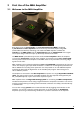
3 First Use of the MEA Amplifier 3.1 Welcome to the MEA Amplifier Raw data from up to 60 electrodes of a microelectrode array (MEA) is amplified by 60 channels of filter amplifiers that are built very small and compact using SMD (Surface Mounted Devices) technology. The small-sized MEA amplifier combines the interface to the MEA probe with the signal filtering and the amplification of the signal. The compact design reduces line pick up and keeps the noise level down.
MEA Amplifier for Inverse Microscopes Manual 3.2 Setting Up and Connecting the MEA Amplifier Warning: Spilled liquid can damage or even completely destroy the electronics of the MEA amplifier. Please be extremely careful when setting up your perfusion system and when starting the perfusion. Take care that the flow rates of the inlet and outlet flow match so that flooding of the amplifier is efficiently prevented. Note: The housing of the MEA amplifiers was optimized for Zeiss Axiovert microscopes.
4 First Tests and Tutorial 4.1 First Functional Tests Each MEA amplifier has been thoroughly tested at the factory site before delivery. However, you may want to perform some tests yourself before you begin your experiment to exclude any damage that might have occurred during transportation, or to fulfill your own guidelines, for instance. Some of the tests will also help you to get to know the basic functions of the hard- and software, like a short tutorial.
MEA Amplifier for Inverse Microscopes Manual The following screen shot shows a recording from a typical MEA amplifier with a test model probe and a sampling rate of 25 kHz. Double-click a channel in the display to have a closer look.
5 Operating the MEA Amplifier 5.1 Signal Amplification and Filters The standard MEA amplifier combines the probe interface with a band pass filter and the signal amplification in one instrument. Different filter settings are used for different applications to enhance the signal-to-noise ratio. The pass band of the filter amplifier should be chosen according to the signal type.
MEA Amplifier for Inverse Microscopes Manual If you use a MEA-System, the isolated power supply IPS10W that is integrated in the data acquisition computer supplies the power for operating the MEA amplifier. The power is distributed along the MCS high grade cable. Please consider that the amplifier can only operate properly if the supply voltage and current specifications are fulfilled, especially if you use a custom power supply. See also the Technical Specifications and the Troubleshooting section. 5.
Operating 5.3 Mounting the MEA Probe and Grounding the Bath Warning: Do not use too much force. Otherwise you could damage the delicate MEA or contact pins of the amplifier. Put the lid of the amplifier only onto a dry and clean area with the bottom side down. Otherwise, you can easily damage the contact pins. 1. Place the MEA amplifier as shown on the photo. Click “Change MEA” in MEA_Select program. Open the lid of the MEA amplifier. 2. Place the MEA probe inside.
MEA Amplifier for Inverse Microscopes Manual Grounding the bath You can ground the bath with a plain silver wire or with an Ag/AgCl pellet. Only the Ag/AgCl electrode provides a stable intrinsic potential. In practice, the plain silver wire will be good for 90 % of applications. If you do not achieve satisfying results with the plain silver wire, try an Ag/AgCl electrode. If you use MEAs with internal reference electrode, you can use the reference electrode for grounding the bath.
Operating 5.4 Stimulation Recommended stimulus protocols for MEA electrodes MCS recommends to use biphasic stimulation pulses only with negative phase first. The duration of each phase should be 100 μs and the amplitude between 100 mV and 3000 mV. (See also Potter, S. M., Wagenaar, D. A. and DeMarse, T. B. (2005). Closing the Loop: Stimulation Feedback Systems for Embodied MEA Cultures. Advances in Network Electrophysiology Using MultiElectrode Arrays. M. Taketani and M. Baudry, Springer; Wagenaar, D. A.
MEA Amplifier for Inverse Microscopes Manual 5.5 Service and Maintenance You should clean the contact pins of the amplifier with a soft tissue and pure (100 %) alcohol from time to time, especially if you have problems with the noise level. It may be necessary after a longer time of operation to replace the contact pins. Replace gold connectors each year or if there are problems with the contacts. Please see the Spare Parts list under "Ordering Information".
6 Troubleshooting 6.1 About Troubleshooting The following hints are provided to solve special problems that have been reported by users. Most problems occur seldom and only under specific circumstances. Please check the mentioned possible causes carefully when you have any trouble with the product. In most cases, it is only a minor problem that can be easily avoided or solved. If the problem persists, please contact your local retailer. The highly qualified staff will be glad to help you.
MEA Amplifier for Inverse Microscopes Manual Contact pin is defective Possible causes: ? The contact pins are contaminated. Clean the contact pins carefully with a smooth and clean tissue and pure (100 %) alcohol. ? The contact pins are damaged. Replace the contact pins carefully. Please see the Spare Parts list under "Ordering Information". Try to handle and clean the contact pins more carefully next time. 6.3 Unsteady Baseline The baseline is unstable, signals are jumping or drifting.
Troubleshooting 6.4 Artifacts on all Channels You see strange artifacts on all channels. This behavior can be caused by an insufficient supply power. Please see the Technical Specifications section. If the voltage drops beyond a critical level, the amplifier cannot operate properly, resulting in artifacts or in a saturation of the amplifier.
MEA Amplifier for Inverse Microscopes Manual 6.5 Liquid Spilled onto Amplifier Warning: Spilled liquid can damage or even completely destroy the electronics of the MEA amplifier. Avoid it by all means. Of course it is best to completely avoid this situation and consider the following instructions as an "emergency measurement" only. Even with this measurement, a severe damage to the instrument cannot be excluded.
7 Appendix 7.1 Technical Specifications 7.1.1 MEA1060-Inv Operating temperature 10 °C to 50 °C Storage temperature 0 °C to 50 °C Dimensions (W x D x H) 165 mm x 165 mm x 20 mm (29 mm with sockets) Weight 800 g Supply voltage (external power supply) ± 6 VDC to ± 9 VDC Supply current max.
MEA Amplifier for Inverse Microscopes Manual 7.1.2 Heating Element The heating element is mounted onto the bottom side of the base plate of the MEA1060 amplifier. It is used for keeping the temperature in the MEA culture chamber stable during recordings. Input voltage max 10 V Input current max 2 A Temperature sensor PT 100 Resistance 15 ± 2 Heating temperature Ambient temperature (min 10 °C) to 50 °C Accuracy 0.1 °C (in the range of 20 °C to 40 °C) Recovery time 0.
Appendix 7.2 Pin Layout 7.2.1 Pin and MEA Layout The layout of standard MEA electrodes follows the scheme of a standard grid: The first digit is the column number, and the second digit is the row number. For example, electrode 23 is positioned in the third row of the second column. The numbering follows the standard order from left to right, and from top to bottom.
MEA Amplifier for Inverse Microscopes Manual Assignment pin to electrode 68-pin socket MEA electrode 68-pin socket MEA electrode 3 47 33 52 4 48 34 51 5 46 35 53 6 45 36 54 7 38 37 61 8 37 38 62 9 28 39 71 10 36 40 63 11 27 41 72 12 17 42 82 13 26 43 73 14 16 44 83 15 35 45 64 16 25 46 74 17 15 47 84 18 14 48 85 19 24 49 75 20 34 50 65 21 13 51 86 22 23 52 76 23 12 53 87 24 22 54 77 25 33 55 66 26 21 56 78 2
Appendix 7.3 Contact Information Local retailer Please see the list of official MCS distributors on the MCS web site. User forum The Multi Channel Systems User Forum provides the opportunity for you to exchange your experience or thoughts with other users worldwide. Mailing list If you have subscribed to the Mailing List, you will be automatically informed about new software releases, upcoming events, and other news on the product line.
MEA Amplifier for Inverse Microscopes Manual USB-MEA-Systems Product Product Number Description USB-MEA-System for upright microscopes USBMEA240Up-4System USB-MEA-System for inverted microscopes USBMEA240Inv-4System MEA Workstation for recording and analyzing data from MEA (microelectrode array) experiments. Data acquisition from up to 240 MEA electrodes, 4 analog channels, 1 audio channel, and 16 digital channels. Integrated analog-digital converter board.
Appendix acquisition and filter amplifier System amplification. 4 additional analog and 1 digital I/O port. Complete with data acquisition computer, software package and accessories. USB 2.0 High Speed data transfer with a sampling rate of up to 40 kHz per channel. USB-MEA256-System with integrated data acquisition and filter amplifier, and advanced perfusion USBMEA256System-E 256-channel recording system with integrated data acquisition from 256MEAs.
MEA Amplifier for Inverse Microscopes Manual Spare Parts Product Product Number Description Heating element with 8 mm bore hole HE-Inv-8 Heating element with 12 mm bore hole HE-Inv-12 Heating element with 23 mm bore hole HE-Inv-23 For MEA1060-Inv/MEA1060-Inv-BC amplifier. Available with bore holes in different sizes, for using smaller or larger microscope objectives. The smallest size has the best temperature controlling properties.
Appendix 60 electrode channels and accessories MEA recording system for inverted microscopes with advanced perfusion, 60 electrode channels MEA60-Inv-2System-E Complete with 5 MEAs, data acquisition computer with MC_Card, 2 x MEA1060-Inv amplifier, MEAS2/1, 2 x TC02, 2 x PH01, power supply, and accessories MEA recording system for upright microscopes with advanced perfusion, 60 electrode channels MEA60-UpSystem-E Complete with 5 MEAs, data acquisition computer with MC_Card, MEA1060-Up amplifier, TC02
Index 33
MC_Card A Aliasing 8 B Band pass band.............................................8 Bandwidth 8 C 10 Configuration 12 Contact Information 5 22 Model Test Probe 19 Mounting MEA Probe ........................................ 10 Noise troubleshooting................................ 14 Noise Level testing ................................................. 6 P F Faraday cage MEA layout ................................................ 20 mounting ..........................................