MEA Amplifier with Blanking Circuit for Inverse Microscopes
Information in this document is subject to change without notice. No part of this document may be reproduced or transmitted without the express written permission of Multi Channel Systems MCS GmbH. While every precaution has been taken in the preparation of this document, the publisher and the author assume no responsibility for errors or omissions, or for damages resulting from the use of information contained in this document or from the use of programs and source code that may accompany it.
Table of Contents 1 1.1 1.2 1.3 Introduction About this Manual Terms of Use for the Program Limitation of Liability 1 1 1 1 2 2.1 2.2 2.3 Important Information and Instructions Operator's Obligations Guarantee and Liability Important Safety Advice 3 3 3 4 3 3.1 3.2 3.3 3.4 First Use of the MEA Amplifier Welcome to the MEA Amplifier Installing the Software MEA_Select Program Setting Up and Connecting the MEA Amplifier 4 4.1 4.2 4.3 4.
MEA Amplifier with Blanking Circuit for Inverse Microscopes iv 6 6.1 6.2 6.3 6.4 6.5 6.6 6.7 6.8 Troubleshooting About Troubleshooting Error Messages Noise on Single Electrodes Unsteady Baseline Artifacts on All Channels Unpredictable Noise and Artifacts Liquid Spilled onto Amplifier Technical Support 41 41 41 41 42 43 44 45 46 7 7.1 7.2 7.3 Appendix Technical Specifications 7.1.1 Pin and MEA Layout 7.1.2 MEA1060-Inv-BC 7.1.
1 Introduction 1.1 About this Manual This manual comprises all important information help the first installation of the hardware and software, and help the daily work with the instrument. It is assumed that you have already a basic understanding of technical and software terms. No special skills are required to read this manual.
2 Important Information and Instructions 2.
MEA Amplifier with Blanking Circuit for Inverse Microscopes 2.3 Important Safety Advice Warning: Make sure to read the following advice prior to install or to use the device and the software. If you do not fulfill all requirements stated below, this may lead to malfunctions or breakage of connected hardware, or even fatal injuries. Warning: Obey always the rules of local regulations and laws. Only qualified personnel should be allowed to perform laboratory work.
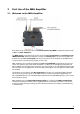
3 First Use of the MEA Amplifier 3.1 Welcome to the MEA Amplifier Raw data from up to 60 electrodes of a microelectrode array (MEA) is amplified by 60 channels of pre- and filter amplifiers. The MEA sensor is placed directly into the small-sized MEA preamplifier with blanking circuit (MEA1060-BC-PA). When the amplifier is closed, the contact pins in the lid of the amplifier are pressed onto the MEA contact pads.
MEA Amplifier with Blanking Circuit for Inverse Microscopes 3.2 Installing the Software System requirements Software: One of the following Microsoft Windows ® operating systems is required: Windows 7, Vista or Windows XP (English and German versions supported). Other language versions may lead to software errors. Hardware: Free RS232 port Installing the software Please check the system requirements before you install the software.
First Use of the MEA Amplifier 3.3 MEA_Select Program MEA Amplifier with blanking circuit (MEA1060-BC) When starting the software program MEA_Select for controlling the blanking circuit of the MEA amplifier the main window appears. You see the electrode button array on the left side. Select the MEA layout from the drop down menu and the electrode button array will be adapted. Click any or “All" button to select any or all electrodes for recording, stimulation or grounding.
MEA Amplifier with Blanking Circuit for Inverse Microscopes A blanking signal (TTL pulse) transiently switch off the input stage of the amplifier during the stimulus, thus avoiding the stimulus artifacts on non-stimulating electrodes. Amplifier saturation is effectively prevented and the recovery time is greatly reduced. It is also possible to record from stimulation electrodes shortly after stimulation.
First Use of the MEA Amplifier The command List Mode opens an additional window: List of Stimulation Patterns. In List Mode you can download a list of up to 50 user defined stimulation patterns. The quantity of 50 patterns is hardware controlled. A stimulation pattern can contain single or multiple electrodes and must get an user defined name. Click "New", and it appears in the small upper window pane.
MEA Amplifier with Blanking Circuit for Inverse Microscopes 3.4 Setting Up and Connecting the MEA Amplifier Warning: Spilled liquid can damage or even completely destroy the electronics of the MEA amplifier. Please be extremely careful when setting up your perfusion system and when starting the perfusion. Take care that the flow rates of the inlet and outlet flow match so that flooding of the amplifier is efficiently prevented.
First Use of the MEA Amplifier Please see also the separate handout "MEA Microelectrode Systems" for setup suggestions with detailed illustrations. The following illustration shows a suggested setup for a standard MEA60-System with stimulus generator and blanking circuit. The following illustration shows a suggested setup for an USB-ME128-System with a MEA1060 amplifier with blanking circuit.
MEA Amplifier with Blanking Circuit for Inverse Microscopes Connecting the amplifier to the stimulus generator The following illustration shows the recommended setup for connecting a stimulus generator to the MEA amplifier with blanking circuit. The amplifier is electrically connected to the stimulus generator only during the short time of the blanking pulse. Therefore, a shielded cable that is usually used for preventing the pick up of noise is not necessary.
4 First Tests and Tutorial 4.1 First Functional Tests Each MEA amplifier has been thoroughly tested at the factory site before delivery. However, you may want to perform some tests yourself before you begin your experiment to exclude any damage that might have occurred during transportation, or to fulfill your own guidelines, for instance. Some of the tests will also help you to get to know the basic functions of the hard- and software, like a short tutorial.
MEA Amplifier with Blanking Circuit for Inverse Microscopes The following screen shot shows a recording from a typical MEA amplifier with a test model probe and a sampling rate of 25 kHz. Double-click a channel in the display to have a closer look.
First Tests and Tutorial 4.3 Computer Connection Testing the computer connection The MEA_Select program automatically detects and lists all serial ports of your computer. 1. Start MEA_Select. Select the serial port to which you have connected the MEA preamplifier (COM1, COM2, and so on) from the drop down list. 1. Click Test Connection. A valid computer connection should be confirmed by OK. If not, please check all cables and connections.
MEA Amplifier with Blanking Circuit for Inverse Microscopes 4.4.1 Operating multiple MEA Amplifiers with one STG It is possible to operate more than one MEA amplifier independently with a single stimulus generator of the 4000 series. To do this, activate the Independent Channel Download feature in the Settings menu of MC_Stimulus II. This feature will allow to download new stimulation paradigms to individual channels without interrupting the ongoing stimulation on other channels.
First Tests and Tutorial To start and stop only the channels associated with one amplifier, use the Start / Stop buttons for individual triggers. Each button controls one trigger and hence all assigned channels. The orange LED indicates ongoing stimulation. In our example, the configuration shown below would mean that amplifiers A, B and D are receiving a stimulation signal, while stimulation for amplifier C is stopped. Triggers 5 to 8 have no function in this example.
MEA Amplifier with Blanking Circuit for Inverse Microscopes 1. Under Stimulation, select Ground. 2. Click any electrodes that you like to ground, for example electrodes 36, 46, and 56. Grounded electrodes show no electrode number, only a blank button. By clicking on one of the grounded electrodes again you can toggle back to recording mode. If you click, for example in Stimulation mode B onto a grounded electrode, you overwrite the grounded mode with Stim. B mode.
First Tests and Tutorial Stimulation without blanking Usually, you will always use the blanking when you stimulate. But it is possible to switch off the blanking for testing your setup. 1. In MC_Rack, bring the triggered display to the front. Make sure you have connected the digital Sync Out output of the stimulus generator to the digital channel 1 (bit 0) of the MC_Card. Otherwise, you have to select the appropriate bit in the Trigger Detector. 2. In MEA_Select, under Blanking, deselect Blanking. 3.
MEA Amplifier with Blanking Circuit for Inverse Microscopes The stimuli are sent to the selected stimulation electrodes. You see stimulus artifacts on all channels. The display operates now in a triggered mode, so that the stimuli appear aligned to the trigger event. Stimulation with blanking 1. Select the Blanking in the MEA_Select program. 2. The Sync Out signal of the stimulus generator triggers not only the stimulation, but the blanking as well.
First Tests and Tutorial You see that there are no stimulus artifacts visible on almost all non-stimulating electrodes, with some residual artifacts on the neighbor electrodes of the stimulating electrode 33. In this example, we have used a Wait of 200 μs. Wait settings You can use the Wait for optimizing the electrode's behavior.
5 Operating the MEA Amplifier 5.1 Signal Amplification and Filters The MEA amplifier with blanking circuit is a 60-channel preamplifier with a broad bandwidth. Filter specifications and gain are defined by the following filter amplifier. Different filter settings are used for different applications to enhance the signal-to-noise ratio. The pass band of the filter amplifier should be chosen according to the signal type.
MEA Amplifier with Blanking Circuit for Inverse Microscopes For information on the gain and filters of the MC_Card data acquisition system, please see the ME- / MEA-System manual. For more information on gain and filters in general, please refer to standard literature or contact your local retailer. If you use a MEA-System, the isolated power supply IPS10W that is integrated in the data acquisition computer supplies the power for operating the MEA amplifier.
Operating the MEA Amplifier DC offset correction The internal baseline restore routine of the preamplifier restores the offset to the ground level, that is, to zero. This has to be a slow process. If the routine corrected too fast, slow signals would be eliminated as well. All electrodes on an array have different DC offsets at the beginning of an experiment.
MEA Amplifier with Blanking Circuit for Inverse Microscopes 5.3 Mounting the MEA Probe and Grounding the Bath Warning: Do not use too much force. Otherwise you could damage the delicate MEA or contact pins of the amplifier. Put the lid of the amplifier only onto a dry and clean area with the bottom side down. Otherwise, you can easily damage the contact pins. Important: Click Change MEA in the MEA_Select program before you remove the shielding or open the amplifier.
Operating the MEA Amplifier Grounding the bath You can ground the bath with a plain silver wire or with an Ag/AgCl pellet. Only the Ag/AgCl electrode provides a stable intrinsic potential. In practice, the plain silver wire will be ok for 90 % of applications. If you do not achieve satisfying results with the plain silver wire, try an Ag/AgCl electrode. If you use MEAs with internal reference electrode, you can use the reference electrode for grounding the bath.
MEA Amplifier with Blanking Circuit for Inverse Microscopes 5.4 Grounding Defective Electrodes You can ground defective electrodes with the MEA_Select program. In the following example, electrodes No. 15, 16, 24, 25, 26, 35, and 47 show a very high noise level. 1. Under Stimulation, select Ground. 2. Click any electrodes that you like to ground. Grounded electrodes show no electrode number, only a blank button. 3. Click Download to download this information on the MEA amplifier.
Operating the MEA Amplifier You can clearly see the difference between the high noise level and the zero line of the grounded electrode.
MEA Amplifier with Blanking Circuit for Inverse Microscopes 5.5 Stimulation Recommended stimulus protocols for MEA electrodes MCS recommends to use only biphasic voltage pulses with the negative phase first. The duration of the pulse should be 100 μs for each phase and the amplitude between 100 mV and 3000 mV. Make sure that the voltage level of the stimulating electrode is zero at the end of the pulse. (See also Potter, S. M., Wagenaar, D. A. and DeMarse, T. B. (2005).
Operating the MEA Amplifier Under Stimulation, select a stimulus input (Stim A or Stim B) and click any buttons on the button array in the MEA layout. Click any electrode that you like to use for stimulation, for example 23 or 73. The stimulation electrodes are marked by a color, that is, blue for stimulus A and red for stimulus B. By clicking on one of the selected electrodes again you can toggle back to recording mode. If you click, for example in Stimulation mode B onto a blue (Stim.
MEA Amplifier with Blanking Circuit for Inverse Microscopes If the List Mode is open, there is an additional button Trace List. If the Trace List button is active all other functions are automatically disabled. The stimulation patterns of the list, created in List Mode, are applied one after the other as stimulation pulse. To control which pattern of the list is reached the name of the stimulus pattern will be highlighted in blue.
Operating the MEA Amplifier 5.6 Stimulus Artifact Suppression (Blanking) A TTL pulse (blanking signal) that has to be timed exactly with the stimulus pulse triggers both the stimulation and the blanking. During the blanking signal, both stimulus inputs are connected to the software-selected stimulating electrodes (A and B), and all MEA electrodes are disconnected from the amplifier.
MEA Amplifier with Blanking Circuit for Inverse Microscopes Wait settings A delay (up to 5000 μs) between stopping stimulation (end of TTL pulse) and restarting the recording can be programmed with the Wait property in the MEA_Select program in order to optimize the blanking. The stimulation electrodes are disconnected from the stimulus input at the end of the trigger signal, and all electrodes are connected to the amplifier input at the end of the Wait period.
Operating the MEA Amplifier Single pulses versus repeated pulses Interestingly, the behavior of MEA electrodes when applying pulses that are repeated after some milliseconds, is much better than when a single pulse is applied. You can observe that the kinetics improve, that is, you need a shorter Wait, following the application of a few pulses.
MEA Amplifier with Blanking Circuit for Inverse Microscopes Behavior of stimulation electrodes Due to the high electric charge that is applied by the stimulus and the general slow kinetics of electrode discharge, the recording from stimulation electrodes is usually not possible shortly after stimulation. You might also observe a minor crosstalk on the two channels that have neighbor tracks to the stimulation electrodes on the MEA. This is considered a normal behavior of the amplifier.
Operating the MEA Amplifier Stimulus artifacts with switched off blanking on a typical non-stimulating 30 μm electrode. The same electrode and pulse protocol, but with blanking. Voltage driven stimulation (1 V, electrode 75) on 30 μm TiN electrodes. A used 60MEA200/30iR-Ti with some defective electrodes was used for this experiment. Defective electrodes 43, 52, 53 were switched to ground in MEA_Select. You see only small artifacts on the channels 65 and 85 with tracks next to the stimulating electrode 75.
MEA Amplifier with Blanking Circuit for Inverse Microscopes 60MEA200/10iR-Ti Voltage driven stimulation (1 V, electrode 33) on 10 μm TiN electrodes. The stimulus artifact suppression is slightly impaired by the higher impedance of the smaller electrodes, but still very good. You see only small artifacts on the channels 21 and 22 with tracks next to the stimulation electrode 33. Pin 15 of the 60MEA200/10iR-Ti was connected to ground.
Operating the MEA Amplifier Standard 60MEA200/30iR-Ti This example shows data from a syncytium of cardiac cells treated with a biphasic 2 V bipolar stimulus pulse field applied to electrodes No 36 and No 46. Please see the schema below. The blanking artefact is in the range of 10 μV that is a negligible value in comparison to the amplitude of the cardiac field potentials ranging from a few hundred μV to several mV. You see the stimulation artefacts on all electrode channels.
MEA Amplifier with Blanking Circuit for Inverse Microscopes 5.8 Service and Maintenance You should clean the contact pins of the amplifier with a soft tissue and pure (100 %) alcohol from time to time, especially if you have problems with the noise level. It may be necessary after a longer time of operation to replace the contact pins. Replace gold connectors each year or if there are problems with the contacts. Please see the Spare Parts list under "Ordering Information".
6 Troubleshooting 6.1 About Troubleshooting The following hints are provided to solve special problems that have been reported by users. Most problems occur seldom and only under specific circumstances. Please check the mentioned possible causes carefully when you have any trouble with the product. In most cases, it is only a minor problem that can be easily avoided or solved. If the problem persists, please contact your local retailer. The highly qualified staff will be glad to help you.
MEA Amplifier with Blanking Circuit for Inverse Microscopes MEA electrode is defective See also the MEA manual. Possible causes: ? The contact pads are contaminated. Clean the contact pads carefully with a swab and pure (100 %) alcohol. ? The contact pads or the electrodes are damaged. Use a new MEA. Try to handle and clean the MEA more carefully next time. Contact pin is defective Possible causes: ? The contact pins are contaminated.
Troubleshooting 6.5 Artifacts on All Channels You see strange artifacts on all channels. This behavior can be caused by an insufficient supply power. Please see the Technical Specifications section. If the voltage drops beyond a critical level, the amplifier cannot operate properly, resulting in artifacts or in a saturation of the amplifier.
MEA Amplifier with Blanking Circuit for Inverse Microscopes 6.6 Unpredictable Noise and Artifacts You use the amplifier for stimulation and you see unpredictable noise and / or artifacts on single or all channels. Current driven stimulation (100 μA, electrode 33) on 10 μm TiN electrodes.
Troubleshooting Due to the higher electrode impedance, the maximum input voltage of the MEA1060-BC amplifier is exceeded when applying a 100 μA pulse, and a proper operation is not possible. Possible causes: ? You use voltage stimuli with a higher amplitude than +/- 5 V. Multi Channel Systems recommends not to exceed the maximum recommended stimulus input range of +/- 5 V (see chapter Technical Specifications in the Appendix). Please adjust the amplitude of the stimuli used.
MEA Amplifier with Blanking Circuit for Inverse Microscopes 6.8 Technical Support Please read the Troubleshooting part of the Manual / Help first. Most problems are caused by minor handling errors. Contact your local retailer immediately if the cause of trouble remains unclear. Please understand that information on your hardware and software configuration is necessary to analyze and finally solve the problem you encounter.
7 Appendix 7.1 Technical Specifications 7.1.1 Pin and MEA Layout The layout of standard MEA electrodes follows the scheme of a standard grid: The first digit is the column number, and the second digit is the row number. For example, electrode 23 is positioned in the third row of the second column. The numbering follows the standard order from left to right, and from top to bottom.
MEA Amplifier with Blanking Circuit for Inverse Microscopes Assignment pin to electrode 68-pin socket pin MEA electrode 68-pin socket pin MEA electrode 3 47 33 52 4 48 34 51 5 46 35 53 6 45 36 54 7 38 37 61 8 37 38 62 9 28 39 71 10 36 40 63 11 27 41 72 12 17 42 82 13 26 43 73 14 16 44 83 15 35 45 64 16 25 46 74 17 15 47 84 18 14 48 85 19 24 49 75 20 34 50 65 21 13 51 86 22 23 52 76 23 12 53 87 24 22 54 77 25 33 55
Appendix 7.1.2 MEA1060-Inv-BC Operating temperature Storage temperature 10 °C to 50 °C 0 °C to 50 °C Dimensions (W x D x H) 165 mm x 165 mm x 20 mm (29 mm with sockets) Weight 800 g Supply voltage (external power supply) ± 6.
MEA Amplifier with Blanking Circuit for Inverse Microscopes 7.1.3 FA60S-BC Operating temperature Storage temperature 10 °C to 50 °C 0 °C to 50 °C Dimensions (W x D x H) 92 mm x 145 mm x 26 mm Weight 450 g Supply voltage (external power supply) ± 6.
Appendix 7.2 Contact Information Local retailer Please see the list of official MCS distributors on the MCS web site. User forum The Multi Channel Systems User Forum provides the opportunity for you to exchange your experience or thoughts with other users worldwide. Mailing list If you have subscribed to the Mailing List, you will be automatically informed about new software releases, upcoming events, and other news on the product line.
MEA Amplifier with Blanking Circuit for Inverse Microscopes 7.3 Ordering Information Product information is subject to change without notice. Please contact your local retailer for pricing and ordering information. MEA Amplifiers Product Product Number Description MEA amplifier for inverted microscopes MEA1060-Inv MEA amplifier for upright microscopes MEA1060-Up Probe interface and 60 channel preand filter amplifier with custom gain and bandwidth.
Appendix USB-MEA-System for inverted microscopes with advanced perfusion USBMEA240-Inv4-System-E are transmitted to any data acquisition computer via USB 2.0 (High Speed). Complete with 5 MEAs, data acquisition computer with preinstalled software, 4 MEA1060-Inv amplifiers for inverted microscopes or 4 MEA1060-Up amplifiers for upright microscopes, 4 temperature controllers, 4 perfusion cannulas with programmable fluid temperature, power supply, and accessories.
MEA Amplifier with Blanking Circuit for Inverse Microscopes Accessories Product Product Number Description Adapter for MEAs with 8 special electrodes for stimulation MEASTIMAdapter For use with MEAs 200/30-Ti-stim or 200/30-ITO-stim, and MEA1060-Inv amplifier.
Appendix Spare Parts Product Product Number Description Heating element with 8 mm bore hole HE-Inv-8 Heating element with 12 mm bore hole HE-Inv-12 Heating element with 23 mm bore hole HE-Inv-23 For MEA1060-Inv/MEA1060-Inv-BC amplifier. Available with bore holes in different sizes, for using smaller or larger microscope objectives. The smallest size has the best temperature controlling properties.
MEA Amplifier with Blanking Circuit for Inverse Microscopes MEA-Systems Product Product Number Description MEA recording system for inverted microscopes, 60 electrode channels MEA60-InvSystem Complete with 5 MEAs, data acquisition computer with MC_Card, MEA1060-Inv amplifier, TC01, power supply, and accessories MEA recording system for inverted microscopes, 60 electrode channels, 2 MEA amplifiers MEA60-Inv2-System Complete with 5 MEAs, data acquisition computer with MC_Card, 2 x MEA1060-Inv amplifie
8 Index 57
MEA Amplifier with Blanking Circuit for Inverse Microscopes 58
3 3D-MEA L 35 A Aliasing 23 Band pass band...........................................23 MC_Card 10 MEA differences in blanking performance35 layout ................................................ 47 mounting .......................................... 26 23 Mounting MEA Probe ........................................ 26 26 N C Change MEA 7 M B Bandwidth List Mode COM serial port ..........................................15 Noise troubleshooting................................
60