MEA Signal Generator
Information in this document is subject to change without notice. No part of this document may be reproduced or transmitted without the express written permission of Multi Channel Systems MCS GmbH. While every precaution has been taken in the preparation of this document, the publisher and the author assume no responsibility for errors or omissions, or for damages resulting from the use of information contained in this document or from the use of programs and source code that may accompany it.
Table of Contents 1 1.1 Introduction About this Manual 1 1 2 2.1 2.2 2.3 Important Information and Instructions Guarantee and Liability Operator's Obligations Important Safety Advice 2 2 2 3 3 3.1 3.2 3.3 MEA Signal Generator Welcome to the MEA Signal Generator Setting Up and Connecting the MEA Signal Generator Handling the MEA-SG 4 4 7 7 4 4.1 4.2 Application Training Demonstration 9 9 9 5 5.1 5.2 Training MC_Rack Summarized information about MC_Rack Getting Started 5.2.1 Starting MC_Rack 5.2.
1 Introduction 1.1 About this Manual This short manual is an addendum to the elaborate MEA Manual. It is strongly recommended to read the MEA manual first, if you utilize the MEA Signal Generator for introducing yourself to the MEA-System. Being already familiar with MEA-System, the MEA-SG will be easy to mount and to handle. It is assumed that you already have a basic understanding of technical and software terms. No special skills are required to read this manual.
2 Important Information and Instructions 2.1 Guarantee and Liability The General conditions of sale and delivery of Multi Channel Systems MCS GmbH always apply. The operator will receive these no later than on conclusion of the contract. Multi Channel Systems MCS GmbH makes no guarantee as to the accuracy of any and all tests and data generated by the use of the device or the software. It is up to the user to use good laboratory practice to establish the validity of his / her findings.
Important Information and Instructions 2.3 Important Safety Advice Warning: Make sure to read the following advice prior to installation or use of the device and the software. If you do not fulfill all requirements stated below, this may lead to malfunctions or breakage of connected hardware, or even fatal injuries. Warning: Always obey the rules of local regulations and laws. Only qualified personnel should be allowed to perform laboratory work.
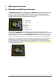
3 MEA Signal Generator 3.1 Welcome to the MEA Signal Generator The MEA Signal Generator is a convenient tool for MEA-System users. As a variable substitute for expensive biology you can use the MEA-SG as you would set up a research experiment. That means you can test your own products and data acquisition settings without using valuable biological samples. It has the advantage that you do not need living material, you reduce the number of animal experiments and save laboratory equipment.
MEA Signal Generator The MEA-SG produces sine waves or real signals in digitized form. These signals are detected as analog signals with the MEA-System. Because of this data source you are able to use and to test the complete MEA-System. The base of a MEA-SG is made of printed circuit board. It shows the MEA standard design with the square recording area build from gold contact pads.
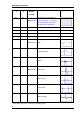
MEA Signal Generator Switch 1 Switch 2 press Button Signal Source n times OFF OFF 1 MEA-SG ON ON OFF Artificial Sine Wave 0.005 Hz Note: sine waves < 1 Hz might not be visible because of the hardware filter bandwidth. 2 Sine Wave 0.01 Hz 3 Sine Wave 0.03 Hz 4 Sine Wave 1.25 Hz 5 Sine Wave 12.
MEA Signal Generator 3.2 Setting Up and Connecting the MEA Signal Generator The MEA-SG is handled in the same manner as a MEA probe for experiments. For detailed information please read MEA Manual. Mounting instructions: 1. Open the lid of the amplifier. 2. Place the MEA-SG inside. The orientation of the chip is not important. 3. Replace the lid and close it carefully. 4. Ground the MEA-SG with a CB-GND cable. 3.
MEA Signal Generator Short circuit Please consider the different levels of amplitudes in electrode displays in direct vicinity side by side regarding to the gold contacts of MEA-SG, but not to the electrode displays. The amplitude alternates in a range of 100 % and 50 %. If there is a short circuit between neighbor pads of gold contact, all electrodes will show the same averaged amplitude. You can see the changing amplitudes in MC_Rack data display best in data row four and five.
MEA Signal Generator 4 Application MEA-SG is suitable for all purposes concerning MEA-System that is why it lends itself to help new users. It is possible to learn about the amplifier and the specific software MC_Rack and MC_DataTool just as well as other software programs. Furthermore you are able to control the operating mode of the amplifier and you have a tool for troubleshooting. 4.
MEA Signal Generator 5 Training MC_Rack With MEA-SG it is easy to train users on the software which is specially made for MEA-Systems: MC_Rack, MEA_Select (if you have an amplifier with blanking circuit), and MC_DataTool. Together with MC_Card and MC_Rack you have a complete set for data acquisition, and MEA-SG generates the data for training instead of an animal experiment. This possibility increases the flexibility of the unpracticed user. Please read the MC_Rack Manual for detailed information.
MEA Signal Generator 5.2 Getting Started Here you will find a short description of basic tasks and tools that are needed. Go through this chapter before you start building a rack. 5.2.1 Starting MC_Rack Double-click the MC_Rack icon or select MC_Rack from the Start menu. The program starts. One dialog box opens automatically. This is your rack. You will now configure your rack and implement the features you need to accomplish the task. Your rack is almost empty, it holds only a Recorder.
MEA Signal Generator 5.2.3 Replaying Data In MC_Rack you can then load the generated data file with another rack later for further offline analysis. The general design of a rack is basically the same for online or for offline analysis. The only difference is that you use the Replayer instead of the MC_Card to generate data streams, which can be processed by other virtual instruments in the rack. First, you define the input data.
MEA Signal Generator 5.2.4 File Information Click File Info. You see the date and time when the file has been recorded and all important information about the conditions which was used. Click Buffer Info. On the left pane, you see the single data stream or several streams which were recorded, the number of channels, the sampling frequency, the gain factor and the data format. 5.2.5 Saving a Rack Save the rack if you would like to keep it for future use. 1. On the File menu, click Save As. 2.
MEA Signal Generator 6 Troubleshooting MEA Amplifier It is possible to control some functions of the MEA amplifier with MEA-SG. Please read also chapter "Troubleshooting" in MEA Manual. Most of the problems with MEA-System are rare, and most are minor problems which can be easily avoided and solved. If a problem persists, please contact your retailer. With MEA-SG you are able to check the electrode pins of your amplifier and the general behavior due to grounding and shielding the system. 6.
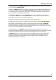
MEA Signal Generator 6.2 Checking the Electrode Pins of the Amplifier Noise in single Electrodes Starting MEA-SG with 12.5 Hz sinus waves you may see the following display: Channel 66, 67, 68 show an significant higher level of noise, channel 78 is completely in saturation. That means, there is a problem with the contact pad of MEA-SG and / or the electrode pins of the amplifier. To test this, turn MEA-SG by 90 degrees.
7 Appendix 7.1 Contact Information Local retailer Please see the list of official MCS distributors on the MCS web site. User forum The Multi Channel Systems User Forum provides the opportunity for you to exchange your experience or thoughts with other users worldwide. Mailing list If you have subscribed to the mailing list, you will be automatically informed about new software releases, upcoming events, and other news on the product line.
Appendix 7.
MEA Signal Generator 7.
60MEA-SG 60MEA-Signal Generator Control button Grounding Socket LED DIP Switch Battery Gold Contact Pads 60MEA-Signal Generator is a very convenient tool for MEA-System and MEA2100-HS(2x)60 users. Use the 60MEA-SG instead of setting up a complete experiment for training, controlling, and troubleshooting purposes. Note: When using a MEA-SG which is not adapted to MEA2100-System, the contact to the internal reference must be disconnected. Otherwise the delivered signals are not acceptable.
60MEA-SG 60MEA-Signal Generator Switch 1 Switch 2 press Button Signal Source Signal Type n times OFF OFF 1 Artificial Sine Wave (1.75 mV) 0.005 Hz 60MEA-SG ON ON OFF Note: sine waves < 1 Hz might not be visible because of the hardware filter bandwidth. 2 Sine Wave 0.01 Hz 3 Sine Wave 0.03 Hz 4 Sine Wave 1.25 Hz 5 Sine Wave 12.
120MEA-SG 120MEA Signal Generator for use with MEA2100-HS120-System Control button LED DIP switch Battery Gold contact pads 120MEA Signal Generator is a convenient tool for MEA2100-System users. Use the 120MEA-SG instead of setting up an experiment with biological sample for training, controlling, and troubleshooting purposes. This reduces the number of animal experiments and saves laboratory equipment. Switch on : Press control button. Switch off : Press control button longer than two seconds.
120MEA-SG 120MEA Signal Generator Switch 1 press Button Switch 2 Signal Source Signal Type n times OFF OFF 1 Artificial Sine Wave (1.75 mV) 0.005 Hz 120MEA-SG ON ON OFF Note: sine waves < 1 Hz might not be visible because of the hardware filter bandwidth. 2 Sine Wave 0.01 Hz 3 Sine Wave 0.03 Hz 4 Sine Wave 1.25 Hz 5 Sine Wave 12.
256MEA-SG 256MEA Signal Generator for use with USB-MEA256-System Control button LED DIP switch Battery Gold contact pads 256MEA Signal Generator is a convenient tool for USB-MEA256-System users. Use the 256MEA-SG instead of setting up an experiment with biological sample for training, controlling, and troubleshooting purposes. This reduces the number of animal experiments and saves laboratory equipment. Switch on : Press control button. Switch off : Press control button longer than two seconds.
256MEA-SG 256MEA Signal Generator Switch 1 Switch 2 press Button Signal Source Signal Type n times OFF OFF 1 Artificial Sine Wave (1.75 mV) 0.005 Hz 256MEA-SG ON ON OFF Note: sine waves < 1Hz might not be visible because of the hardware filter bandwidth. 2 Sine Wave 0.01 Hz 3 Sine Wave 0.03 Hz 4 Sine Wave 1.25 Hz 5 Sine Wave 12.
Appendix 19