
User Manual

60-6wellMEA
© 2013 Multi Channel Systems MCS GmbH
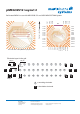
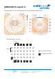
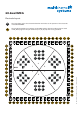
Electrode layout inside each well Example: Well A
3131 4444
4343
42424141 5252 5151 5353
5454
A 1A 1
A 2A 2
A 3A 3
A 4A 4
A 5A 5
A 6A 6
A 7A 7
A 8A 8 A 9A 9
Well A
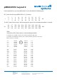
MEA amplifier pin numbers
Overwiev:
MEA amplifier pin numbers (digit)
and correspondent electrode identifier
code (letter-digit) inside each well.
A B C D E F
1 43 63 65 56 36 34
2 42 82 76 57 17 23
3 51 83 77 48 16 22
4 44 71 75 55 28 24
5 52 73 87 47 26 12
6 53 64 66 46 35 33
7 31 62 85 68 37 14
8 41 72 86 58 27 13
9 54 74 78 45 25 21
GND 32 61 84 67 38 15
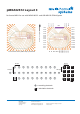
Well BWell F
Well C
Well D
Well E
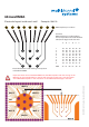
Electrode identifier code refering to the position
in the 60-6wellMEA.
MCS
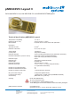
Important: Please insert the 60-6wellMEA into the MEA amplifier with the writing on the
MEA chip (in this example MCS) on the left side viewed from the front, with the sockets
of the MEA1060 amplifier or the articulation of the MEA2100 headstage in the back.