Microelectrode Array (MEA) Manual
Information in this document is subject to change without notice. No part of this document may be reproduced or transmitted without the express written permission of Multi Channel Systems MCS GmbH. While every precaution has been taken in the preparation of this document, the publisher and the author assume no responsibility for errors or omissions, or for damages resulting from the use of information contained in this document or from the use of programs and source code that may accompany it.
Microelectrode Arrays (MEAs) — Overview Table of Contents 1 Introduction 6 1.1 About this Manual 6 2 Important Information and Instructions 7 2.1 Operator's Obligations 7 2.2 Guarantee and Liability 7 2.3 Important Safety Advice 8 3 Microelectrode Arrays (MEAs) — Overview 9 3.1 Extracellular Recording with Microelectrode Arrays 3.2 MEA Design and Production 10 3.3 Electrodes, Tracks, and Insulation 11 4 MEA Types and Layouts 12 4.1 Standard Electrode Numbering 13 4.
MEA Manual 5 MEA Handling 35 5.1 Hydrophilic Surface Treatment 35 5.1.1 Plasma Cleaning 35 5.1.2 Protein Coating 35 5.1.3 Preculturing 36 5.2 36 5.2.1 Sterilization with Ethanol and UV Light 36 5.2.2 Steam Sterilization (Autoclavation) 36 5.2.3 Dry-Heat Sterilization 36 5.2.4 Sterilization with Hot Water 36 5.3 MEA Storage 37 5.4 MEA Coating 37 5.5 4 Sterilization 5.4.1 Coating with Nitrocellulose 37 5.4.2 Coating with Polyethyleneimine (PEI) plus Laminin 38 5.4.
Microelectrode Arrays (MEAs) — Overview 7 Recording with MEAs 50 7.1 Mounting the MEA 50 7.1.1 Cleaning the Contact Pads 50 7.1.2 Positioning the MEA 50 7.1.3 Grounding the Bath 50 7.2 General Performance / Noise Level 51 8 Stimulation 53 8.1 Using MEA Electrodes for Stimulation 53 8.2 Capacitive Behavior of Stimulating Electrodes 54 8.3 Aspects of Electrode Size and Material 55 8.4 Recommended Stimulus Amplitudes and Durations 56 9 Troubleshooting 57 9.
MEA Manual 1 Introduction 1.1 About this Manual The MEA manual comprises all important information about the microelectrode arrays (MEA) for use with (USB-) MEA- or ME-Systems from Multi Channel Systems. The MEA manual focuses on general information on the MEA design, use, and handling, and more specific information on different MEA types. It also includes recommendations on sterilization, coating, and cleaning procedures, from scientifical papers or from recommendations of other MEA users.
Microelectrode Arrays (MEAs) — Overview 2 Important Information and Instructions 2.
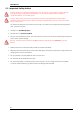
MEA Manual 2.3 Important Safety Advice Warning: Make sure to read the following advice prior to install or to use the device and the software. If you do not fulfill all requirements stated below, this may lead to malfunctions or breakage of connected hardware, or even fatal injuries. Warning: Obey always the rules of local regulations and laws. Only qualified personnel should be allowed to perform laboratory work. Work according to good laboratory practice to obtain best results and to minimize risks.
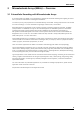
MEA Manual 3 Microelectrode Arrays (MEAs) — Overview 3.1 Extracellular Recording with Microelectrode Arrays A microelectrode array (MEA) is an arrangement of typically 60 electrodes allowing the targeting of several sites in parallel for extracellular recording and stimulation. Cell lines or primary cell preparations are cultivated directly on the MEA. Freshly prepared slices can be used for acute recordings, or can be cultivated as organotypic cultures (OTC) on the MEA.
MEA Manual 3.2 MEA Design and Production A standard MEA biosensor has a square recording area of 700 μm to 5 mm length. In this area, 60 electrodes are aligned in an 8 x 8 grid with interelectrode distances of 100, 200, or 500 μm. Planar TiN (titanium nitride) electrodes are available in sizes of 10, 20, and 30 μm, and three-dimensional TiN electrodes have a diameter of > 20 μm at the base with a very fine tip. Standard MEAs are useful for a wide variety of applications.
MEA Manual 3.3 Electrodes, Tracks, and Insulation Microfold structures result in a large surface area that allows the formation of electrodes with an excellent signal to noise ratio without compromising on the spatial resolution. TiN (titanium nitride) is a very stable material that, for example, is also widely used for coating heavy equipment. All MEAs with TiN electrodes have a long life and can be reused several times if handled with care.
MEA Manual 4 MEA Types and Layouts Various types of MEA biosensors are available for all kind of extracellular multi channel recordings. Typical MEAs for in vitro applications have 60 microelectrodes arranged in an 8 x 8 layout grid embedded in a transparent glass substrate. You can cultivate the tissue or cell culture directly on the MEA. EcoFlexand FlexMEAs are made for in vivo and in vitro applications.
MEA Manual Square MEAs with TiN (Titanium nitride) electrodes in 50 x 50 μm square size in a 8 x 8 layout grid. PEDOT-CNT MEAs with carbon nanotube – poly 3,4-ethylene-dioxythiophene electrodes and gold tracks and contact pads have very low impedance values of approximately 20 kThey are ideal for stimulation and have excellent biocompatibility and cell adhesion.
MEA Manual 4.2 Standard MEA 60MEA100/10-ITO, 60MEA200/10iR-ITO, 60MEA200/30iR-ITO, 60MEA100/10iR-TI, 60MEA200/10-Ti, 60MEA200/30-Ti, 60MEA200/10iR-TI, 60MEA200/30iR-Ti,60MEA500/10iR-Ti, 60MEA500/30iR-Ti Standard MEAs have 60 electrodes in an 8 x 8 layout grid with electrode diameters of 10 μm or 30 μm, and interelectrode distances of 100 μm, 200 μm. The MEAs with an interelectrode distance of 500 μm have a 6 x 10 layout grid.
MEA Manual 4.3 High Density MEA: 60HDMEA 60HDMEA30/10iR-ITO 10 μm electrodes are arranged in two recording fields with 5 x 6 electrodes each. The interelectrode spacing is only 30 μm center to center. The very high electrode density of the two recording fields on a 60HDMEA is only possible by the special TiN electrode material and production process. This MEA type is especially useful for applications, where a high spatial resolution is critical, for example, for multitrode analysis.
MEA Manual 4.4 Hexa MEA: 60HexaMEA 60HexaMEA-Ti, 60HexaMEA-ITO, 60HexaMEA40/10iR-ITO Electrode layout for 60HexaMEA-Ti and 60HexaMEA-ITO. Electrode layout for 60HexaMEA40/10iR-ITO. HexaMEAs feature a hexagonal layout, perfect for recording from retina. The 60 electrodes of 60HexaMEA-Ti or 60HexaMEA-ITO are aligned in a special configuration with varying electrode diameters (10, 20, 30 μm) and interelectrode distances (see upper pictures).
MEA Manual 4.5 Thin MEA: 60ThinMEA 60ThinMEA200/30iR-ITO, 60ThinMEA30/10iR-ITO 60ThinMEAs are only 180 μm "thick", ideally suited for high-resolution imaging. 60ThinMEAs are like standard MEAs, but the electrodes are embedded in a very thin and delicate glass substrate on a robust ceramic carrier. The thin glass allows the use of oil immersion objectives with a high numerical aperture.
MEA Manual 4.6 Eco MEA: 60EcoMEA 60EcoMEA, 60EcoMEA-Glass 60EcoMEAs are available on opaque printed circuit board (PCB) and on transparent glass base (60EcoMEAGlass). They are low price variants for medium throughput applications like small screens where material costs play a bigger role than in more scientific MEA applications. 60EcoMEAs are opaque and are therefore useful only for applications where you do not need a visual control under a microscope, for example, for established cell cultures.
MEA Manual 4.7 Stimulation MEA: 60StimMEA 60StimMEA200/30-Ti Stimulation MEAs are available in 8 x 8 standard MEA layout with additional 16 stimulation electrodes. Eight pairs of the stimulation electrodes are big and square, the other eight pairs have the same size as the recording electrodes (30 μm). For perfect use with the MEA1060 amplifiers is it necessary to connect adapters: MEA-STIM-ADPT-INV-BC for MEA1060-Inv-BC amplifiers, MEA-STIM-ADPT-Up(BC) for MEA1060Up(BC) amplifiers.
MEA Manual 4.8 Perforated MEA: 60pMEA 60pMEA200/30iR-Ti 60pMEA100/30iR-Ti Acute slice recordings on common glass MEAs are done from the cells at the bottom of the slice, which are in contact with the MEA electrodes. These cells get less oxygen and nutrients from the perfusion medium, and therefore are likely to give smaller signals and might eventually die first.
MEA Manual 4.9 Perforated MEAs for Use with MEA2100-32-System and USB-MEA32-STIM4-System pMEA-32S12-L1, pMEA-32S12-L2, pMEA-32S12-L3, pMEA-32S12-L4 pMEA-32S12-Lx For the USB-MEA32-STIM4-System small perforated MEAs have been designed. Please see USB-MEA32STIM4 manual for detailed information. Additionally the MEA2100-32-System is adapted for these small type of MEA. The pMEAs are different in size, but identical in function to the regular pMEAs.
MEA Manual 4.10 MEA with 6 Wells: 60-6wellMEA 60-6wellMEA200/30iR-Ti 60-6wellMEAs are MEA chips with six independent culture chambers, separated by a macrolon ring. Inside each well, in between the marked two bars coming out of the circle in the middle of the MEA, there is a field of nine electrodes with an internal reference electrode. The electrode in the center of the MEA is for grounding. 60-6wellMEAs are developed, for example, for safety-pharmacological screenings of drug induced QT-prolongation.
MEA Manual 4.11 256MEA for Use with USB-MEA256-System 256MEA30/8-ITO, 256MEA60/10iR-ITO, 256MEA100/30-ITO, 256MEA200/30-ITO, and 256ThinMEA The 256MEAs have to be used with the USB-MEA256-System. Please refer to the USB-MEA256-System manual for detailed information. The 256MEA contains 252 recording, and four ground electrodes arranged in a 16 x 16 layout grid embedded in a transparent glass substrate. The contact to the amplifier is provided by a double ring of contact pads around the rim of the MEA.
MEA Manual 4.12 MEA with 6 Wells for Use with USB-MEA256-System 256-6wellMEA200/30iR-Ti The 256-6wellMEA200/30iR-ITO has 256 electrodes and has to be used with the USB-MEA256-System. Please refer to the USB-MEA256-System manual for detailed information. The dimension of the glass carrier is 49 x 49 x 1 mm as usual. The MEAs with 6 wells are stable in a temperature range from 0 ° - 125 °C.
MEA Manual 4.13 MEA with 9 Wells for Use with USB-MEA256-System 256-9wellMEA300/30iR-ITO The 256-9wellMEA300/30iR-ITO has 256 electrodes and has to be used with the USB-MEA256-System. Please refer to the USB-MEA256-System manual for detailed information. The dimension of the glass carrier is 49 x 49 x 1 mm as usual. The MEAs with 9 wells are stable in a temperature range from 0 ° - 125 °C.
MEA Manual 4.14 120MEA with for Use with MEA2100-120-System 120MEA200/30iR-Ti, 120MEA100/30iR-Ti, 120pMEA200/30iR-Ti 120MEA200/30iR-Ti 120pMEA200/30iR-Ti (electrode field with perforation) The 120MEA200/30iR-Ti has 120 electrodes and can only be used with the MEA2100-System connected to a headstage HS120 with 120 electrodes. Please refer to the MEA2100-System manual for detailed information. The dimension of the glass carrier is 49 x 49 x 1 mm as usual.
MEA Manual 4.15 Quadrant MEA: 60-4QMEA1000 60-4QMEA1000iR-Ti The 60-4QMEA1000 has 60 electrodes organized in four quadrants (13 electrodes each) with a center line (7 electrodes). The electrode diameter is 30 μm, and the interelectrode distance varies: Inside the quadrants the distance is 200 μm, from quadrant to quadrant the distance is 1000 μm, and to the center line it is 500 μm. The 60-4QMEA1000 is available with an internal reference electrode.
MEA Manual 4.16 Square MEA: 60SquareMEA 60SquareMEA200/50iR-Ti 60SquareMEAs have 60 electrodes in an 8 x 8 layout grid with square electrode of 50 x 50 μm size and interelectrode distances of 200 μm. They are available with an internal reference electrode. You can connect the internal reference electrode directly to the amplifier's ground and will not need silver pellets for grounding the bath anymore. The flat, square electrodes are made of titanium nitride (TiN).
MEA Manual 4.17 PEDOT-CNT MEAs: 60PedotMEA 60PedotMEA200/30iR-Au Carbon nanotube stucture of PEDOT electrodes. 60PedotMEAs have - like standard MEAs - 59 electrodes and one reference electrode that are arranged in an 8 x 8 layout grid with electrode diameters of 30 μm and interelectrode distances of 200 μm. The flat, round electrodes are made of PEDOT-CNT carbon nanotube – poly 3,4-ethylene-dioxythiophene. Contact pads and track material is made of titanium nitride (TiN) covered by a layer of gold (Au).
MEA Manual 4.18 FlexMEA FlexMEAs are made of flexible polyimide foil, perfect for in vivo and specific in vitro applications. Only 12 μm "thick" and weighing less than 1 g, the FlexMEA biosensor is very thin and light weight. The FlexMEAs are available with 32 (64) recording electrodes plus two (four) indifferent reference electrodes and two (four) ground electrodes in a 6 x 6 (8 x 9) electrodes grid. More layouts can be provided on request.
MEA Manual FlexMEA36 The FlexMEA36 has 32 recording electrodes plus two internal reference electrodes and two ground electrodes in a 6 x 6 electrodes grid. The titanium nitride electrodes have a diameter of 30 μm, and the distance between the electrodes is 300 μm. The polyimide foil is perforated with holes of 30 μm diameter, ensuring optimal tissue contact.
MEA Manual 4.19 EcoFlexMEA EcoFlexMEAs are made of flexible polyimide (Kapton). They are less flexible as FlexMEAs, but therefore more robust in handling and sterilization. With a thickness of 50 μm and low weight the EcoFlexMEA is perfect for in vivo and specific in vitro applications, respectively. The EcoFlexMEA is available with 24 or 36 electrodes, two internal reference electrodes, and two ground electrodes. Custom layouts can be provided on request.
MEA Manual EcoFlexMEA36 The EcoFlexMEA36 has 32 recording electrodes, two internal reference electrodes, and two ground electrodes in a 6 x 6 electrode grid. The recording electrodes have a diameter of 50 μm, the distance between the electrodes from center to center is 300 μm. The electrodes, contact pads and track material are made of pure gold. EcoFlexMEA36 is stable at a temperature range from 0 °C to 125 °C and can be autoclaved.
MEA Manual 4.20 MEA Signal Generator: 60MEA-SG 60MEA-SG The 60MEA-Signal Generator is a convenient tool for MEA-Systems first time users. It can replace a MEA for learning and / or teaching purposes. The device has the same dimensions and contact pad layout as a 60-channel MEA chip, and is compatible with all MEA1060 amplifier types and with the MEA2100-System with 60-channel headstage, MEA2100-HS60 or MEA2100-HS2x60. The MEA-SG produces sine waves, or replays a variety of biological signals.
MEA Manual 5 MEA Handling Warning: If possible, use only liquids or cleaning solutions with a neutral pH = 7 on MEAs. Do not expose MEAs with a silicon nitride insulation or TiN electrodes to basic liquids (pH > 7) or aggressive detergents for a longer period of time. Basic or aggressive liquids may damage TiN electrodes irreversibly.
MEA Manual 5.1.3 Preculturing Another pragmatic method is to coat the hydrophobic MEAs and to plate the cell cultures on the MEA, and let it grow for some days (up to weeks) until the cells have transformed the surface so that it is sufficiently hydrophilic. The “preculture” will generally show very bad growth and viability, and needs to be discarded before plating the culture that will be used for experiments. Please note that the MEA and the electrode performance may suffer under cell culturing.
MEA Manual 5.3 MEA Storage To maintain a hydrophilic surface after hydrophilization, it is recommended to store the MEAs filled with water until use. Dry MEAs will get hydrophobic again after some time. Store MEAs filled with sterile distilled water at 4 °C in the dark (that is, in the fridge, to prevent microbiological contaminations) to maintain a hydrophilic surface. 5.
MEA Manual Nitrocellulose solution For preparing a stock solution, dissolve a piece of 1 cm2 nitrocellulose membrane in 10 ml methanol. Stock solutions may be stored at room temperature in polystyrene tubes. For the working solution, dilute the stock solution 10 : 1 with methanol. You can adjust the concentration to meet your requirements. Procedure 1. Directly before use, pipette 3 – 5 μl of the working solution onto the recording field. The recording field should be completely covered. 2.
MEA Manual PEI stock solution 0.05 – 0.1 % PEI dissolved in borate buffer. Laminin solution 20 μg/ml laminin in plating medium. Procedure Note: It is necessary to thoroughly rinse off unbound PEI from the plates before use, as dried PEI is toxic. 1. Pipette 500 μl PEI solution onto the MEA. The recording field should be completely covered. 2. Incubate at RT for 1 h, or at 4 °C over night. 3. Remove the PEI solution and thoroughly rinse 4 x with distilled water. 4. Air-dry the MEA. 5.
MEA Manual Procedure 1. Incubate the MEA with polyornithine solution at RT for 2 – 3 hours or overnight at 4 °C. 2. Aspirate the polyornithine solution and rinse the MEA 3 x with distilled water before direct use or before the following coating with laminin. MEAs coated with polyornithine can be stored at 4 C for several weeks. 3. Incubate pre-coated MEA with laminin solution for at least 1 h. 4. Aspirate the laminin solution and directly plate cells.
MEA Manual 5.4.5 Coating with Poly-D-Lysine (plus Fibronectin) This coating method is used, for example, for culturing dissociated suprachiasmatic nucleus (SCN) neurons (on standard 60MEA200/30). It is very stable and therefore especially useful for long-term cultures. Materials Poly-D-lysine 5 mg / 10 mL (= 0.05 % w/v) stock solution (Sigma-Aldrich, Inc.
MEA Manual Procedure 1. Cover the MEA surface with 300 μl fibronectin solution and incubate the MEA at 37 °C for at least 1 h. 2. Aspirate the solution and rinse the MEA 2 x with PBS (phosphate buffered saline). 3. Plate the cells onto the MEA immediately after coating. Literature Ulrich Egert, Thomas Meyer (2004); Heart on a Chip — Extracellular multielectrode recordings from cardiac myocytes in vitro, "Methods in Cardiovascular Research", S. Dhein and M. Delmar (eds.) 5.4.
MEA Manual 5.5 Cleaning of used MEAs 5.5.1 General Recommendations for Cleaning MEAs The cleaning procedure depends on the kind of coating and on the kind of biological preparation. In the following, a few general considerations are listed. If you have recorded from an acute slice without coating, you can simply rinse the MEA with distilled water and the MEA should be fine. If necessary, the MEA can then be cleaned with any cleaning agent, for example, a standard dish-washing detergent.
MEA Manual 5.5.5 Cleaning of FlexMEAs FlexMEAs made of polyimide foil have a temperature range from 10 – 125 °C. They can be sterilized by autoclavation. Please do not use an ultrasonic bath for FlexMEAs! Rinse with distilled water first, optional with ethanol 70%. 5.5.6 Removing Nitrocellulose Coating Note: It is very important that you clean MEAs that have been coated with nitrocellulose and remove all biological material first before removing the coating.
MEA Manual 5.5.8 MEA Cleaning with Terg-A-Zyme Materials: Terg-A-Zyme Distilled water (Sigma-Aldrich, Inc., Z273287) Terg-A-Zyme solution: Prepare a 1 % solution of Terg-A-Zyme in distilled water. Method: 1. Place the MEA in 1 % Terg-A-Zyme solution overnight at room temperature. 2. Apply gentle shaking or rocking, if possible. 3. After Terg-a-Zyme treatment, rinse the MEA thoroughly with distilled water. (Terg-A-Zyme solution can be stored at 4 °C and reused for about a week). 4.
Recording with MEAs 6 Culture Chamber and Ring Options You have several options regarding culture chamber interface rings (without ring, glass ring, plastic ring without and with thread) and culture chambers, which are especially useful for long-term cultures or experiments. For more details or pricing information, please ask your local retailer. 6.1 MEA2100-CO2-C The MEA2100-CO2-C is a climate chamber for MEA2100-Systems.
MEA Manual 6.3 MEA Culture Chamber with Lid Another possibility is to use a MEA culture chamber with lid (available from Multi Channel Systems), which is suitable for all MEAs with plastic ring and thread. It can be adapted by inserting metal perfusion cannulas for setting up a continuous perfusion. 6.4 Culture Chamber for 9-Well MEAs The culture chamber ring 9well-CC for 256-9wellMEAs is suitable for the 9well macrolon quadrat (available from Multi Channel Systems).
Recording with MEAs 6.6 Ring Options The following table shows all available ring options. Glass rings (-gr) are available in two heights of 6 or 12 mm. Plastic rings (-pr) are available in four heights and without or with thread (-pr-T). The triangle(-tcr) and round (-rcr) chamber rings are suitable for the 6 well MEAs, the macrolon quadrates (-mq) for the 252-9wellMEAs.
MEA Manual 7 Recording with MEAs 7.1 Mounting the MEA 7.1.1 Cleaning the Contact Pads You should always clean the contact pads with alcohol before placing it into the MEA amplifier. Even if you do not see any contaminations, a very thin grease layer from touching the pads with bare fingers, for example may be present and results in a bad contact between the pads and the amplifier pins. A bad contact will result in an increased noise level on the affected channel.
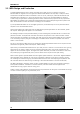
Recording with MEAs 7.2 General Performance / Noise Level You can test a MEA before use by filling it with a standard saline buffer, for example PBS (phosphate buffered saline), and recording the noise level of the MEA and the amplifier. MEA amplifiers have a maximum noise level of +/– 8 μV. The noise level on the MEA depends on the electrode size and material. The smaller the electrode, the higher is the noise level.
MEA Manual Electrodes 43, 52, 53, and 84 show an increased noise level after a longer cycle of use. The bath was grounded with the internal reference electrode 15. Time axis: 1000 ms, voltage axis: 50 μV. You should ground some of the electrodes if you want to use this MEA for recording. Same MEA, zoom to single channel # 22. Time axis: 500 ms, voltage axis: 20 μV. Same MEA after grounding defective electrodes. Time axis: 1000 ms, voltage axis: 100 μV.
Stimulation 8 Stimulation 8.1 Using MEA Electrodes for Stimulation You can use any MEA electrode(s) for stimulation. Simply connect the stimulus generator outputs to the MEA amplifier. Please see the manual for the respective MEA amplifier and stimulus generator for more details. As an alternative, you can also use special 60StimMEA with four pairs of large (250 x 50 μm) stimulating electrodes and a special stimulation adapter, or target cells with an external electrode for stimulation.
MEA Manual 8.2 Capacitive Behavior of Stimulating Electrodes Regarding the generally used stimulus pulses, stimulating electrodes behave as plate capacitors. The charge cannot flow back to the stimulus generator due to the high output resistance and thus is kept in the electrode. The electrode needs a quite long time to discharge itself after stimulation. As a result, stimulus artifacts interfere with the recording, and electrodes deteriorate over time due to electrolysis.
Stimulation 8.3 Aspects of Electrode Size and Material Titanium nitrite (TiN) electrodes are generally more robust than electrodes from other materials, for example platinum (Pt). In the Appendix, you find safe charge injection limit curves that document maximum current and stimulus durations for standard TiN electrodes. Please note that these curves document the limits. Stimulus pulses should be kept safely below these limits. The safe charge injection limit of platinum (0.
MEA Manual 8.4 Recommended Stimulus Amplitudes and Durations The higher the amplitude and the longer the stimulus, the higher is the impact on the electrode performance. Therefore, the amplitude and duration should be as low as possible. It is advisable to start with a low amplitude and duration, and then increase it slowly until responses are evoked. The allowed product of amplitude and duration is directly proportional to the electrode surface.
Troubleshooting 9 Troubleshooting 9.1 About Troubleshooting The following hints are provided to solve special problems that have been reported by users. Most problems occur seldom and only under specific circumstances. Please check the mentioned possible causes carefully when you have any trouble with the product. In most cases, it is only a minor problem that can be easily avoided or solved. If the problem persists, please contact your local retailer. The highly qualified staff will be glad to help you.
MEA Manual 9.3 Noise on Single Electrodes The noise level on single electrodes is significantly higher than expected or you see artifact signals. In the following example (60MEA200/30, filled with PBS (phosphate buffered saline), silver pellet as bath electrode, shielded), electrodes No. 53, 63, 73, 45, 55, 48, 58 show a high noise level. Possible causes: ? The electrode or the contact pin of the amplifier may be defective. To test this, do the following. 1.
Troubleshooting MEA is defective MEAs wear out after multiple uses or over a longer time of use, for example for long-term cultures. This is considered a normal behavior. MEAs are also easily damaged by mishandling, for example if wrong cleaning solutions or too severe cleaning methods are used or if the recording area is touched. If you observe a bad long-term performance of MEAs, consider a more careful handling. Possible causes: ? The contact pads are contaminated.
MEA Manual 9.4 Overall Noise / Unsteady Baseline The baseline is unstable, signals are jumping or drifting. Possible causes: ? Bath electrode is not connected to ground. Connect the internal or external bath electrode to one of the ground inputs of the amplifier. ? AgCl bath electrode needs is not well-chlorided. Rechloride the electrode or use a new one. ? 50 Hz hum: 50 Hz is the frequency of mains power in Europe.
Troubleshooting The next screen shot shows the effect of shielding: The noise level is neglectible, and the baseline is steady. The shielding has been achieved with a metal plate connected to the metal part of the 68-pin MCS high grade cable connector and placed above the amplifier. You could also use aluminum foil or a Faraday cage for the same effect, for example. 9.
Appendix 10 Appendix 10.1 Contact Information Local retailer Please see the list of official MCS distributors on the MCS web site. User forum The Multi Channel Systems User Forum provides an excellent opportunity for you to exchange your experience or thoughts with other users worldwide. Mailing List If you have subscribed to the mailing list, you will be automatically informed about new software releases, upcoming events, and other news on the product line.
MEA Manual 10.
Safe Charge Injection Limits of Micro Electrode Arrays with TiN Electrodes (diameter: 30 µm) s af e c harg e in je c tio n lim its m ax. p uls e am p litud e [µ A ] 2000 1500 1000 500 0 0 50 100 150 250 300 tim e [µ s ] 350 400 450 500 s a f e c h a rg e in je c tio n lim its 400 m a x. p uls e am p litu d e [µ A ] 200 350 300 250 200 150 100 50 0 500 1000 1500 2000 2500 3000 s af e c harg e in je c tio n lim its 60 m ax.
Safe Charge Injection Limits of Micro Electrode Arrays with TiN Electrodes (diameter: 10 µm) s a f e c h a rg e in je c tio n lim its m a x. p uls e am p litu d e [µ A ] 2000 1500 1000 500 0 0 5 10 15 25 tim e [µ s ] 30 35 40 45 50 s af e c harg e inje c tio n lim its 400 m ax. p uls e am p litud e [µ A ] 20 350 300 250 200 150 100 50 0 50 100 150 200 250 300 s af e c harg e in je c tio n lim its 60 m ax.
Appendix 10.
Standard 60MEA 60MEA200/10iR-ITO, 60MEA200/30iR-ITO, 60MEA100/10iR-ITO, 60MEA100/10-ITO, 60MEA100/10iR-Ti, 60MEA200/30-Ti, 60MEA200/10iR-Ti, 60MEA200/30iR-Ti 49.0 mm 0.2 mm 5.4 mm 2.2 mm 10 / 30 μm 21 31 41 51 61 71 12 22 32 42 52 62 72 82 13 23 33 43 53 63 73 83 14 24 34 44 54 64 74 84 REF15 25 35 45 55 65 75 85 16 26 36 46 56 66 76 86 17 27 37 47 57 67 77 87 28 38 48 58 68 78 49.
Standard 60MEA MEA pins, 1 dim. 23 33 33 63 63 38 22 22 22 72 72 39 21 12 12 82 82 40 73 73 41 83 83 42 64 64 43 74 74 44 84 84 45 85 85 46 75 75 47 65 65 48 86 86 49 76 76 50 87 87 51 MEA pins, 1 dim. 24 25 26 27 28 29 30 31 32 33 34 35 36 37 MEA pins, 2 dim.
60MEA500/10iR-Ti 60MEA500/10iR-Ti, 60MEA500/30iR-Ti MEA with electrode layout grid 6 x 10 Technical Specifications Micro Electrode Array with 6 x 10 Layout Temperature compatibility Dimension (W x D x H) Base material Track material Contact pads Electrode diameter Interelectrode distance (centre to centre) Electrode height Electrode type Isolation type Electrode impedance Electrode layout grid Number of recording electrodes Number of reference electrodes 0 - 125 °C 49 mm x 49 mm x 1 mm Glass Ti (Titanium
60MEA500/10iR-Ti Electrode layout grid 6 x 10 MEA pins 33 21 32 31 44 43 41 42 52 51 53 54 61 62 71 63 Electrode # I1 K1 H2 K2 I2 I3 K3 H3 H4 K4 I4 I5 K5 H5 K6 I6 500 μm 22 G3 G4 72 71 H6 82 I5 I6 G5 73 53 54 63 H3 H4 H5 H6 G6 83 32 42 52 62 82 F4 64 G1 G2 G3 G4 G5 G6 F5 74 13 23 22 72 73 83 F1 F2 F3 F4 F5 F6 F6 84 14 24 34 64 74 84 E6 85 E2 E3 E4 E5 E6 25 35 65 75 85 E5 75 D1 D2 D3 D4 D5 D6 E4 65
60HighDenseMEA 60HD30/10iR-ITO 60 High Density Microelectrode Array with Internal Reference Electrode Technical Specifications: 60HighDenseMEA Temperature compatibility Dimension (W x D x H) 0 - 125 °C 49 mm x 49 mm x 1 mm Base material Contact pads and track material Electrode diameter Interelectrode distance (centre to centre) Distance between electrode fields Electrode height Electrode type Isolation type Electrode impedance Electrode layout grid Number of recording electrodes Number of reference elec
60HighDenseMEA 60HD30/10iR-ITO Electrode Layout MEA pins Electrode # 33 21 A3L C3L 32 31 A4L A5L 44 43 41 42 B4L B5L C4L C5L 52 51 53 54 61 62 71 63 C1R C2R B1R B2R A1R A2R C3R A3R 22 B3L B3R 72 12 A2L Left electrode field Right electrode field 23 A1L A4R 82 A5R 73 A1L A2L A3L A4L A5L Electrode # A1R A2R A3R A4R A5R 13 B2L 23 12 33 32 31 MEA pins 61 62 63 82 73 B4R 83 34 B1L B1L B2L B3L B4L B5L B1R B2R B3R B4R B5R B5R 64 34 13 22 44 43
60HexaMEA40/10 60HexaMEA40/10iR-ITO 60 Hexa Microelectrode Array Technical Specifications 60HexaMEA40/10 Temperature compatibility Dimension (W x D x H) 0 - 125 °C 49 mm x 49 mm x 1 mm Base material Contact pads and track material Electrode diameter Interelectrode distance (centre to centre) Electrode height Electrode type Isolation type Electrode impedance Electrode layout grid Number of recording electrodes Number of reference electrodes Glass ITO (Indium tin oxide) 10 μm 40 μm Planar TiN (Titanium ni
60HexaMEA40/10 60HexaMEA40/10iR-ITO Electrode Layout MEA pins 33 21 32 31 44 43 41 42 52 51 53 54 61 62 71 63 Electrode # C3 B2 A1 D5 A2 B3 C4 A3 B4 A4 C5 B5 A5 E4 B6 C6 MEA pins 32 44 42 51 61 Electrode # A1 A2 A3 A4 A5 22 B1 12 C2 23 C1 22 21 43 52 54 71 B1 B2 B3 B4 B5 B6 23 13 D3 12 C1 34 D2 24 D1 10 μm 33 C2 41 C3 53 C4 72 C7 82 D7 73 E5 83 D8 64 E6 74 40 μm 63 C5 D6 C6 82 40 μm C7 24 34 13 14 31 72 73 64 D1
60HexaMEA 60HexaMEA-ITO 60HexaMEA-Ti 60 Hexa Microelectrode Array 10 30 60 20 90 30 μm 90 μm Technical Specifications 60HexaMEA Temperature compatibility Dimension (W x D x H) Thickness (region of electrodes) Base material Contact pads Track material Electrode diameter Interelectrode distance (centre to centre) Electrode height Electrode type Isolation type Electrode impedance 0 - 125 °C 49 mm x 49 mm x 1 mm Electrode layout grid Number of recording electrodes Number of reference electrodes Glass
60HexaMEA 60HexaMEA-ITO 60HexaMEA-Ti Electrode Layout MEA1060 pins 33 Electrode # B7 22 B1 21 32 31 44 43 41 42 B9 B10 C5 C4 Electrode # C5 C3 C2 C6 MEA1060 pins 31 12 B8 23 B6 12 34 B3 24 B4 14 B5 15 A10 B5 14 B C 35 A7 C6 44 42 21 43 B6 B7 23 33 C1 C7 C9 20 μm C7 D4 54 71 B10 32 41 C1 51 61 D1 D6 63 82 72 83 D10 84 D9 64 74 34 13 A10 22 A1 38 F1 77 E10 86 65 25 35 27 A3 17 36 26 A8 17 A6 A5 E1 15 A2 16 F10 47 F2 67 A6 26 F11 45 D5 D4
60ThinMEA30/10iR-ITO 60ThinMEA30/10iR-ITO Technical Specifications 60ThinMEA30/10iR-ITO Temperature compartibility Dimension (W x D x H) “Thickness” Base material Contact pads and track material Electrode diameter Interelectrode distance (centre to centre) Distance between electrode fields Electrode height Electrode type Isolation type Electrode impedance Electrode layout grid Number of recording electrodes Number of reference electrodes 0 - 125 °C 49 mm x 49 mm x 1 mm 180 μm (Glass part) Glass on ceramic
60ThinMEA30/10iR-ITO 60ThinMEA30/10iR-ITO MEA pins Electrode # 33 21 A3L C3L 32 31 A4L A5L 44 43 41 42 B4L B5L C4L C5L 52 51 53 54 61 62 71 63 C1R C2R B1R B2R A1R A2R C3R A3R 22 B3L B3R 72 12 A2L Left electrode field A4R 82 Right electrode field 23 A1L A5R 73 A1L A2L A3L A4L A5L 13 B2L 23 12 33 32 31 34 B1L B1L B2L B3L B4L 34 13 22 C1L C2L 14 24 C2L 14 C1L 25 D2L A1R A2R A3R A4R A5R 61 62 63 82 73 B4R 83 B5L B1R B2R B3R B4R B5R B5R 64
60ThinMEA 60ThinMEA30/10-ITO 60ThinMEA100/10-ITO 60ThinMEA200/30iR-ITO 33 21 32 31 44 43 41 42 52 51 53 54 61 62 71 63 22 72 12 82 21 31 41 51 61 71 12 22 32 42 52 62 72 82 13 23 33 43 53 63 73 83 73 23 13 34 24 14 15 83 64 74 14 24 34 44 54 64 74 84 65 75 85 15 25 35 45 55 35 16 26 36 46 56 66 76 86 16 17 27 37 47 57 67 77 87 84 85 25 75 65 86 26 17 76 28 38 48 58 68 78 87 27 77 36 28 37 38 45 46 48 47 57 58 56 55 68 67 78 66 60
60EcoMEA Low priced Microelectrode Array on PCB Base 33 21 32 31 44 43 41 42 52 51 53 54 61 62 71 63 22 72 12 82 21 31 41 51 61 71 12 22 32 42 52 62 72 82 13 23 33 43 53 63 73 83 73 23 13 34 24 64 74 14 14 24 34 44 54 64 74 84 15 REF 25 35 45 55 65 75 85 35 16 26 36 46 56 66 76 86 16 17 27 37 47 57 67 77 87 25 83 85 75 26 17 84 65 86 76 28 38 48 58 68 27 78 87 77 36 28 37 38 45 46 48 47 57 58 56 55 68 67 78 66 60EcoMEA on PCB b
60EcoMEA-Glass Low priced Microelectrode Array on Glass Base 33 21 32 31 44 43 41 42 52 51 53 54 61 62 71 63 22 72 12 82 21 31 41 51 61 71 12 22 32 42 52 62 72 82 13 23 33 43 53 63 73 83 73 23 13 34 24 14 15 25 83 64 74 14 REF 24 34 44 54 64 74 84 65 75 85 25 35 45 55 85 75 35 16 26 36 46 56 66 76 86 16 17 27 37 47 57 67 77 87 26 17 84 65 86 76 28 38 48 58 68 27 78 87 77 36 28 37 38 45 46 48 47 57 58 56 55 68 67 78 66 60EcoMEA on g
60StimMEA 60StimMEA200/30-ITO 60StimMEA200/30-Ti 33 21 32 31 44 43 41 42 52 51 53 54 61 62 71 63 12 82 60 electrodes Microelectrode Array with 16 additional stimulation electrodes.
60pMEA100/30iR-Ti 60pMEA100/30iR-Ti Perforated Microelectrode Array with 6 x 10 electrode layout grid. Perforated MEAs for use with MEA1060 amplifiers equipped with a perfusion ground plate (PGP) or a MEA2100 headstage with a perfusion element (PE). The perforation allows a perfusion of the tissue from both sides of the pMEA.
60pMEA100/30iR-Ti 21 32 31 44 43 41 42 52 Electrode # 31 43 42 41 52 51 53 63 51 61 53 54 61 62 71 62 71 72 73 81 MEA pins MEA pins Electrode # 60pMEA100/30iR-Ti 33 32 82 63 22 33 83 72 12 21 91 82 23 11 101 73 13 22 11 21 31 41 51 61 71 81 91 101 92 34 12 23 12 21 44 41 51 54 71 82 73 102 64 12 22 32 42 52 62 72 82 92 102 83 24 23 34 13 33 31 43 53 61 63 83 64 93 14 13 13 23 33 43 53 63 73 83 93 103
60pMEA200/30iR-Ti 60pMEA200/30iR-Ti 33 21 32 31 44 43 41 42 52 51 53 54 61 62 71 63 72 22 82 12 21 31 41 51 61 71 12 22 32 42 52 62 72 13 23 33 43 53 63 73 83 14 24 34 44 54 64 74 84 84 25 35 45 55 65 75 85 85 16 26 36 46 56 66 76 86 17 27 37 47 57 67 77 87 28 38 48 58 68 78 23 13 34 73 82 24 25 REF 75 65 35 16 64 74 14 15 83 26 86 76 17 87 27 77 36 28 37 38 45 46 48 47 57 58 56 55 68 67 78 66 Perforated Microelectrode Array in
pMEA32S12 Layout 1 Perforated MEA for use with MEA2100-32- and USB-MEA32-STIM4-System Technical Specifications pMEA32S12 Layout 1 Temperature compatibility Dimension (W x D x H) Base material 10 - 50 °C 49 mm x 25 mm x 1.8 mm Polyimide foil on ceramic carrier with perforation Perforation: Total area of holes Diameter of the holes 0.
pMEA32S12 Layout 1 A 7 150 μm A 1 A10 CH24 CH27 CH28 CH30 A13 A16 A19 A22 A25 A28 A31 A 6 A 9 A12 A15 A18 A21 A24 A27 A30 A 2 A 5 A 8 A11 A14 A17 A20 A23 A26 A29 A32 30 μm 45 ° S 2 A = recording electrode S 4 50 μm S = stimulation electrode S 3 125 μm S 6 S 5 S 8 S 7 Electrode layout in the grid S10 S 9 S12 S11 Multi Channel Systems MCS GmbH Aspenhaustrasse 21 72770 Reutlingen Germany Fon +49-7121-9 09 25- 0 Fax +49-7121-9 09 25-11 © 2013 Multi Channel Systems MC
pMEA32S12 Layout 1 Perforated MEA for use with MEA2100-32- and USB-MEA32-STIM4-System MC_Rack channel map: pMEA-32S12-L1_12x3.cmp 6 15 8 9 14 10 7 11 4 5 12 13 3 16 2 1 29 31 30 17 19 28 18 26 27 21 23 24 20 22 32 25 The MC_Rack channel map is build analog to the layout of the recording electrodes in the grid.
pMEA32S12 Layout 2 Perforated MEA for use with MEA2100-32- and USB-MEA32-STIM4-System Technical Specifications pMEA32S12 Layout 2 Temperature compatibility Dimension (W x D x H) Base material 10 - 50 °C 49 mm x 25 mm x 1.8 mm Polyimide foil on ceramic carrier with perforation Perforation: Total area of holes Diameter of the holes 0.
pMEA32S12 Layout 2 CH26 CH25 CH23 CH22 CH21 CH20 CH18 REF CH19 CH29 CH31 CH32 CH16 CH13 CH12 CH11 CH14 CH24 CH27 CH28 CH30 The oval area of the pMEA chip is perforated STG15 STG14 STG21 CH 4 STG16 STG11 CH 5 CH 3 CH 1 STG25 STG23 STG22 CH 6 CH 7 STG24 STG26 STG13 STG12 CH 9 CH15 CH10 CH 8 CH 2 Direction to Amplifier CH17 Perforated MEA for use with MEA2100-32- and USB-MEA32-STIM4-System Electrode layout in the grid 90 μm 90 μm S5 S2 100 μm S1 S3 S7 50 μm A 1 S9 A 4 A 7 A
pMEA32S12 Layout 2 Perforated MEA for use with MEA2100-32- and USB-MEA32-STIM4-System MC_Rack channel map: pMEA-32S12-L2_12x3.cmp 5 3 7 1 2 9 4 8 6 10 14 15 11 13 12 16 19 17 29 21 20 18 22 25 23 31 32 26 27 28 24 30 The MC_Rack channel map is build analog to the layout of the recording electrodes in the grid.
pMEA32S12 Layout 3 Perforated MEA for use with MEA2100-32- and USB-MEA32-STIM4-System Technical Specifications pMEA32S12 Layout 3 Temperature compatibility Dimension (W x D x H) Base material 10 - 50 °C 49 mm x 25 mm x 1.8 mm Polyimide foil on ceramic carrier with perforation Perforation: Total area of holes Diameter of the holes 0.
pMEA32S12 Layout 3 STG11 STG14 90 μm A 7 A10 A13 A16 A19 A22 A25 A28 A31 100 μm 150 μm A 3 A 2 CH25 CH 6 CH 4 90 μm A 1 CH22 STG13 STG12 STG15 CH10 CH 8 STG21 CH24 CH27 CH28 CH30 STG24 STG26 STG16 CH16 CH13 CH12 CH11 CH14 CH15 CH 5 CH 3 CH 1 STG25 STG23 STG22 CH31 CH32 CH 7 CH19 CH29 CH 9 CH26 The oval area of the pMEA chip is perforated A 4 CH23 CH20 CH21 REF CH17 CH 2 Direction to Amplifier CH18 Perforated MEA for use with MEA2100-32- and USB-MEA32-STIM4-System
pMEA32S12 Layout 3 Perforated MEA for use with MEA2100-32- and USB-MEA32-STIM4-System MC_Rack channel map: pMEA-32S12-L3_12x3.cmp 19 16 14 13 17 29 15 18 12 10 21 20 8 23 11 6 22 4 2 26 25 9 31 7 5 32 27 3 24 28 1 30 The MC_Rack channel map is build analog to the layout of the recording electrode in the grid.
pMEA32S12 Layout 4 Perforated MEA for use with MEA2100-32- and USB-MEA32-STIM4-System Technical Specifications pMEA32S12 Layout 4 Temperature compatibility Dimension (W x D x H) Base material 10 - 50 °C 49 mm x 25 mm x 1.8 mm Polyimide foil on ceramic carrier with perforation Perforation: Total area of holes Diameter of the holes 0.
pMEA32S12 Layout 4 CH18 CH17 CH19 CH23 STG26 STG24 STG11 REF CH 8 CH10 CH28 CH27 The oval area of the pMEA chip is perforated STG12 CH25 CH24 STG25 CH 4 CH 6 STG23 CH22 CH16 CH20 CH26 CH21 CH30 CH 7 CH 9 STG13 STG16 STG21 STG22 CH15 CH14 CH11 CH12 CH13 CH 2 CH 5 CH31 CH32 CH 3 STG15 CH29 CH 1 Direction to Amplifier STG14 Perforated MEA for use with MEA2100-32- and USB-MEA32-STIM4-System Electrode layout in the grid 100 μm S9 S11 A29 A25 A21 A17 A30 A26 A22 A31 A27 A23
pMEA32S12 Layout 4 Perforated MEA for use with MEA2100-32- and USB-MEA32-STIM4-System MC_Rack channel map: pMEA-32S12-L4_8x4.cmp 11 2 8 3 14 13 10 5 15 12 1 7 29 4 6 9 19 16 20 27 23 31 30 28 17 32 21 24 18 22 26 25 The MC_Rack channel map is build analog to the layout of the recording electrode in the grid.
60-6wellMEA Electrode Layout A1 The letter-digit code is the electrode identifier and refers to the position of the electrode in the 60-6wellMEA. 33 33 The specified amplifier pin numbers are the MEA-System channel numbers that are used in MC_Rack program. The pin numbers 32, 61, 84, 67, 38, and 15 are grounded.
60-6wellMEA Electrode layout inside each well 44 43 41 42 52 51 53 54 MEA amplifier pin numbers Overwiev: MEA amplifier pin numbers (digit) and correspondent electrode identifier code (letter-digit) inside each well.
60-6wellMEA F6 A6 A7 A8 A9 F5 F8 F7 E9 F4 C2 E7 E4 C6 C3 D9 D8 D7 D6 D5 D4 D3 D2 D1 E1 C1 C5 E5 E8 E6 C4 C8 E2 C7 C D C9 E3 B6 E B B9 F B8 A B3 F9 F2 A5 B5 F1 A4 B2 A3 B4 A2 B7 MCS A1 B1 F3 MC_Rack Electrode Layout Channel Map F1 34 F2 23 F3 22 A1 43 A2 42 A3 51 B1 63 B2 82 B3 83 The letter-digit code is the electrode identifier and refers to the position of the electrode in the 60-6wellMEA.
256MEA 256MEA30/8iR-ITO 256MEA60/10iR-ITO 256MEA100/30iR-ITO 256MEA200/30iR-ITO 2 Connector 1 1 64 63 64 63 1 2 ABCDEFGH I KL MNOPR Connector 4 1 2 3 4 5 6 7 8 9 10 11 12 13 14 15 16 Connector 2 1 2 3 4 5 6 7 8 9 10 11 12 13 14 15 16 ABCDEFGH I KL MNOPR 2 1 63 64 63 64 Connector 3 1 2 256 Microelectrode Array for use with USB-MEA256-System.
256MEA A2 B1 C2 E5 D3 D1 E4 E2 F5 F3 F1G4 G2 H5 H3 H1 H7 I6 I2 I4 B2 C3 C1 G7 D2 G6 E3 E1 F4 F2 G5 G3 G1 H4 H2 H6 I 3 I 5 K 2 K 4 L 1 L 3 L 5 M 2 M 4 N 1 N3 L 6 O 2 N 4 I7 I1 K 1 K 3 K 5 L 2 L 4 M 1 M 3 K 6 N 2 I 8 O 1 GND GND D 4 P2 P1 A3 B3 O3 R2 H8 F6 R3 P3 B4 C4 K7 M5 F7 A4 P4 O4 B1 C1 D1 E1 F1 G1 H1 I1 K1 L1 M1 N1 O1 P1 A2 B2 C2 D2 E2 F2 G2 H2 I2 K2 L2 M2 N2 O2 P2 R2 A3 B3 C3 D3 E3 F3 G3 H3 I3 K3 L3 M3 N3 O3 P3 R3 A4 B4 C4 D4 E4 F4 G
256MEA Stimulation Connector Socket 1 Electrode Stim.
256ThinMEA 256ThinMEA200/30iR-ITO 2 Connector 1 1 64 63 64 63 1 2 ABCDEFGH I KL MNOPR Connector 4 1 2 3 4 5 6 7 8 9 10 11 12 13 14 15 16 Connector 2 1 2 3 4 5 6 7 8 9 10 11 12 13 14 15 16 ABCDEFGH I KL MNOPR 2 1 63 64 Thin microelectrode array with 16 x 16 layout. The electrodes are embedded in a very thin glass substrate on a robust ceramic carrier. Contact pads and tracks are made from transparent ITO for high resolution imaging.
256ThinMEA A2 B1 C2 E5 D3 D1 E4 E2 F5 F3 F1G4 G2 H5 H3 H1 H7 I6 I2 I4 B2 C3 C1 G7 D2 G6 E3 E1 F4 F2 G5 G3 G1 H4 H2 H6 I 3 I 5 K 2 K 4 L 1 L 3 L 5 M 2 M 4 N 1 N3 L 6 O 2 N 4 I7 I1 K 1 K 3 K 5 L 2 L 4 M 1 M 3 K 6 N 2 I 8 O 1 GND GND D 4 P2 P1 A3 B3 O3 R2 H8 F6 R3 P3 B4 C4 K7 M5 F7 A4 P4 O4 B1 C1 D1 E1 F1 G1 H1 I1 K1 L1 M1 N1 O1 P1 A2 B2 C2 D2 E2 F2 G2 H2 I2 K2 L2 M2 N2 O2 P2 R2 A3 B3 C3 D3 E3 F3 G3 H3 I3 K3 L3 M3 N3 O3 P3 R3 A4 B4 C4 D4 E4 F4
256ThinMEA Stimulation Connector Socket 1 Electrode Stim.
256-6wellMEA 256-6wellMEA200/30iR-ITO-rcr 256-6wellMEA200/30iR-ITO-tcr 2 1 6-Well Microelectrode Array for use with USB-MEA256-System. Connector 1 64 63 1 2 64 63 B F E Connector 2 Connector 4 A D C 63 64 2 1 63 64 The MEA is not symmetrical and has to be inserted into the amplifier with well A on top as shown in the picture.
256-6wellMEA F74 A44 A35 A16 A15 A14 A13 A12 A11 A21 A31 A41 A51 A61 A71 A72 A73 A74 A75 A76 A55 A45 B14 B13 B12 B11 B21 B31 B41 B51 B61 GND A46 A36 A26 A25 A24 A34 A23 A22 A33 A32 A42 A43 A52 A53 A62 A63 A64 A54 A65 A66 A56 B24 B34 B23 B22 B33 B32 B42 B43 B52 B53 B71 GND F54 B72 B62 F63 F73 B73 B63 F62 F72 B74 B54 F53 F71 B75 B64 F52 F61 A11 A21 A31 A41 A51 A61 A71 A12 A22 A32 A42 A52 A62 A72 A13 A23 A33 A43 A53 A63 F42 F51 B76 B65 B66 B44 F43 F41 F32 F31 B56 B55 A73 B46 B45
256-6wellMEA Stim Sock et 1 2 3 4 5 6 7 8 9 10 11 12 13 14 15 16 17 18 19 20 21 22 23 24 25 26 27 28 29 30 31 32 33 34 35 36 37 38 39 40 41 42 43 44 45 46 47 48 49 50 51 52 53 54 55 56 57 58 59 60 61 62 63 GND Connector 1 Elect Sprin rode g ID Con.
256-6wellMEA Tables: Electrode ID and number of stimulation connector socket in well A, B, and C. Electrode ID and number of stimulation connector socket in well D, E, and F. Well A Stimulation Socket Conn. 1 No. 1 Conn. 1 No. 2 Conn. 1 No. 3 Conn. 1 No. 4 Conn. 1 No. 5 Conn. 1 No. 6 Conn. 1 No. 7 Conn. 1 No. 8 Conn. 1 No. 9 Conn. 1 No. 10 Conn. 1 No. 11 Conn. 1 No. 12 Conn. 1 No. 13 Conn. 1 No. 14 Conn. 1 No. 15 Conn. 1 No. 16 Conn. 1 No. 17 Conn. 1 No. 18 Conn. 1 No. 19 Conn. 1 No. 20 Conn. 1 No.
256-9wellMEA 256-9wellMEA300/30iR-ITO-w/o 256-9wellMEA300/30iR-ITO-mq 2 9-well Microelectrode Array for use with USB-MEA256-System. 1 Connector 1 64 63 1 2 MCS A B C D E F G H J Connector 2 Connector 4 64 63 63 64 2 1 The MEA is not symmetrical and has to be inserted into the amplifier with the writing MCS on top as shown in the picture beside.
256-9wellMEA Macrolon Quadrat MCS 9 mm Slot to insert an O-ring for membrane covering. 0.8 mm 0.8 mm 6.5 mm 1.2 mm A B C D E F G H J 1.2 mm 6.5 mm 9-Well macrolon quadrat for 256-9wellMEA. 14.60 mm 23.50 mm 49 mm 256-9wellMEA with macrolon quadrat and 9well-CC ring to use it as a culture chamber. Please insert a foil between quadrat and ring.
256-9wellMEA E31 A34 A24 A33 A13 A12 A21 A31 A42 A52 A43 AS2 A64 A55 A45 B34 B24 BS1 B13 B12 B21 B31 B42 B52 B43 BS2 B64 B55 B45 E42 E52 GND A35 A25 A14 AS1 A23 A22 A32 A41 A51 A62 A63 A53 A54 A44 B35 B25 B14 B33 B23 B22 B32 B41 B51 B62 B63 B53 B54 B44 E41 E51 E62 E43 GND E32 C35 ES2 E22 E21 C25 C34 E23 E12 C14 C24 D45 E13 C23 CS1 D55 D44 A21 A31 A41 A51 B21 B31 B41 B51 A D64 D54 D53 DS2 D43 D63 D52 D62 B A25 A35 A45 A55 D42 D51 B25 B35 B45 B55 C21 C31 C41 C51 C C25 C35 C45 C55 C33 C13 C
256-9wellMEA Tables: Electrode ID and number of stimulation connector socket in well A, B, and C. Electrode ID and number of stimulation connector socket in well D, E, and F. Electrode ID and number of stimulation connector socket in well G, H, and J. Well A Stimulation Socket Conn. 1 No. 7 Conn. 1 No. 12 Conn. 1 No. 10 Conn. 1 No. 5 Conn. 1 No. 14 Conn. 1 No. 11 Conn. 1 No. 9 Conn. 1 No. 6 Conn. 1 No. 3 Conn. 1 No. 16 Conn. 1 No. 13 Conn. 1 No. 8 Conn. 1 No. 4 Conn. 1 No. 1 Conn. 1 No. 15 Conn. 1 No.
256-9wellMEA Stim Sock et 1 2 3 4 5 6 7 8 9 10 11 12 13 14 15 16 17 18 19 20 21 22 23 24 25 26 27 28 29 30 31 32 33 34 35 36 37 38 39 40 41 42 43 44 45 46 47 48 49 50 51 52 53 54 55 56 57 58 59 60 61 62 63 GND Connector 1 Elect Sprin rode g ID Con.
120MEA 120MEA200/30iR-Ti 120MEA100/30iR-ITO 120MEA for Use with MEA2100-120-System with 12 x 12 electrode grid C3 E5 C2 D2 D3 E4 D1 E2 E3 F4 E1 F2 F3 F5 G6 F1 G1 G5 G3 G2 H1 G4 H3 H2 J1 H4 J3 J2 K2 J4 46 47 48 49 50 51 52 53 54 55 56 57 58 59 60 61 62 63 64 65 66 67 68 69 70 71 72 73 74 75 45 44 43 B4 42 A4 41 D5 40 C5 39 B5 38 A5 37 D6 36 C6 35 B6 34 A6 33 E6 32 F6 31 E7 30 A7 29 B7 28 C7 27 D7 26 A8 25 B8 24 C8 23 D8 22 A9 21 B9 20 C9 19 E8 18 B10 17 C10 16 B3 D4 C4 GND GND REF REF
120MEA 120MEA200/30iR-Ti 120MEA100/30iR-ITO C3 E5 C2 D2 D3 E4 D1 E2 E3 F4 E1 F2 F3 F5 G6 F1 G1 G5 G3 G2 H1 G4 H3 J1 H2 H4 J3 J2 K2 J4 46 47 48 49 50 51 52 53 54 55 56 57 58 59 60 61 62 63 64 65 66 67 68 69 70 71 72 73 74 75 45 GND 44 C4 43 B4 42 A4 41 D5 40 C5 39 B5 38 A5 37 D6 36 C6 35 B6 34 A6 33 E6 32 F6 31 E7 30 A7 29 B7 28 C7 27 D7 26 A8 25 B8 24 C8 23 D8 22 A9 21 B9 20 C9 19 E8 18 B10 17 C10 16 GND GND 76 B3 D4 K3 77 78 H5 79 K4 80 L4 81 M4 82 J5 83 K5 84 L5 85 M5 86 J6 87 K6 88
120MEA 120MEA200/30iR-Ti 120MEA100/30iR-ITO Electrode Layout Table: Hardware ID and Electrode ID HW ID EL ID HW ID EL ID HW ID EL ID HW ID EL ID 120 119 118 117 116 115 114 113 112 111 110 109 108 107 106 105 104 103 102 101 100 99 98 97 96 95 94 93 92 91 90 89 88 87 86 85 84 83 82 81 80 79 78 77 76 75 74 73 72 71 70 69 68 67 66 65 64 63 62 61 60 59 58 57 56 55 54 53 52 51 50 49 48 47 46 45 44 43 42 41 40 39 38 37 36 35 34 33 32 31 30 29 28 27 26 25 24 23 22 21 20 19 18 17 16 15 14 13 12 11 10 9 8 7
pMEA200/30iR-Ti 120pMEA for Use with MEA2100-120-System Layout with 12 x 12 electrode grid C3 E5 C2 D2 D3 E4 D1 E2 E3 F4 E1 F2 F3 F5 G6 F1 G1 G5 G3 G2 H1 G4 H3 H2 J1 H4 J3 J2 K2 J4 46 47 48 49 50 51 52 53 54 55 56 57 58 59 60 61 62 63 64 65 66 67 68 69 70 71 72 73 74 75 45 44 C4 43 B4 42 A4 41 D5 40 C5 39 B5 38 A5 37 D6 36 C6 35 B6 34 A6 33 E6 32 F6 31 E7 30 A7 29 B7 28 C7 27 D7 26 A8 25 B8 24 C8 23 D8 22 A9 21 B9 20 C9 19 E8 18 B10 17 C10 16 B3 D4 Technical Specifications 120pMEA200/3
120pMEA200/30iR-Ti C3 E5 C2 D2 D3 E4 D1 E2 E3 F4 E1 F2 F3 F5 G6 F1 G1 G5 G3 G2 H1 G4 H3 J1 H2 H4 J3 J2 K2 J4 46 47 48 49 50 51 52 53 54 55 56 57 58 59 60 61 62 63 64 65 66 67 68 69 70 71 72 73 74 75 45 GND D4 44 C4 43 B4 42 A4 41 D5 40 C5 39 B5 38 A5 37 D6 36 C6 35 B6 34 A6 33 E6 32 F6 31 E7 30 A7 29 B7 28 C7 27 D7 26 A8 25 B8 24 C8 23 D8 22 A9 21 B9 20 C9 19 E8 18 B10 17 C10 16 GND GND 76 B3 REF D1 E1 F1 G1 H1 J1 REF A1 C2 D2 E2 F2 G2 H2 J2 K2 B3 C3 D3 E3 F3 G3 H
120pMEA200/30iR-Ti Electrode Layout Table: Hardware ID and Electrode ID HW ID EL ID HW ID EL ID HW ID EL ID HW ID EL ID 120 119 118 117 116 115 114 113 112 111 110 109 108 107 106 105 104 103 102 101 100 99 98 97 96 95 94 93 92 91 90 89 88 87 86 85 84 83 82 81 80 79 78 77 76 75 74 73 72 71 70 69 68 67 66 65 64 63 62 61 60 59 58 57 56 55 54 53 52 51 50 49 48 47 46 45 44 43 42 41 40 39 38 37 36 35 34 33 32 31 30 29 28 27 26 25 24 23 22 21 20 19 18 17 16 15 14 13 12 11 10 9 8 7 6 5 4 3 2 1 G8 G12 G11
60-4QMEA1000 60-4QMEA1000iR-Ti Four Quadrants Microelectrode Array 1000 μm 200 μm 200 μm 200 μm 200 μm 500 μm 500 μm 1000 μm 500 μm 200 μm 200 μm 1000 μm 200 μm 30 μm Technical Specifications 60-4QMEA1000 Temperature compatibility Dimension (W x D x H) 0 - 125 °C 49 mm x 49 mm x 1 mm Base material Track material Contact pads Electrode diameter Interelectrode distance (centre to centre) Electrode height Electrode type Isolation type Electrode impedance Electrode layout grid Number of recording e
60-4QMEA1000 60-4QMEA1000iR-Ti Electrode layout MEA pins 33 21 32 31 44 43 41 42 52 51 53 54 61 62 71 63 Electrode # B1 B2 A2 A3 B3 C3 D3 D4 C4 D5 C5 B5 A5 A6 B6 B7 12 23 13 A5 A6 31 61 62 B1 B2 B3 B5 B6 B7 33 21 44 54 71 63 C1 C2 C3 C4 C5 C6 C7 12 22 43 52 53 72 82 D1 D2 D3 D4 D5 D6 D7 13 23 41 42 51 73 83 E6 E7 64 74 C2 C1 D2 D1 34 E2 24 E1 14 G4 15 REF 25 A3 E1 E2 24 34 500 μm 200 μm F4 1000 μm 22 A2 3
60SquareMEA200/50iR-Ti Microelectrode Array with 60 square electrodes 21 31 41 51 61 71 12 22 32 42 52 62 72 82 13 23 33 43 53 63 73 83 14 24 34 44 54 64 74 84 25 35 45 55 65 75 85 16 26 36 46 56 66 76 86 17 27 37 47 57 67 77 87 28 38 48 58 68 78 REF Technical Specifications 60SquareMEA200/50iR-Ti Temperature compatibility Dimension (W x D x H) Base material Track material Contact pads Electrode square size Interelectrode distance (centre to centr
60SquareMEA200/50iR-Ti Microelectrode Array with 60 square electrodes 21 32 31 44 43 41 42 52 Electrode # 21 32 31 44 43 41 42 52 51 51 53 54 61 62 71 53 54 61 62 71 MEA pins MEA pins Electrode # Standard electrode layout grid 8 x 8 33 33 63 63 22 22 72 72 12 12 82 82 23 23 73 73 13 13 83 83 34 34 64 64 74 74 84 84 85 85 75 75 65 65 86 86 76 76 87 87 14 14 15 REF 41 51 61 71 12 22 32 42 52 62 72 82 13 23 33 43 53 63
60PedotMEA200/30iR-Au Microelectrode Array with PEDOT-CNT Electrodes 33 21 32 31 44 43 41 42 52 51 53 54 61 62 71 63 22 72 12 82 21 31 41 51 61 71 12 22 32 42 52 62 72 82 13 23 33 43 53 63 73 83 73 23 13 34 24 14 15 64 74 24 34 44 54 64 74 84 REF (15) 25 35 45 55 65 75 85 14 84 85 75 25 35 16 26 36 46 56 66 76 86 16 17 27 37 47 57 67 77 87 26 17 83 65 86 76 28 38 48 58 68 78 27 87 77 36 28 37 38 45 46 48 47 57 58 56 55 68 67 78 66 C
FlexMEA36 Flexible Microelectrode Array with 36 electrodes for use with 32-Channel Miniature Preamplifier MPA32I-Flex or with the ADPT-FM-32 adapter and the standard MPA32I. 2200 Dimensions in μm 31000 3000 Technical Specifications FlexMEA36 Temperature compatibility Dimension (W x D) Thickness of the electrode field Weight 10 - 40 °C 31 mm x 18.
FlexMEA36 Electrode Layout 30 m 300 m 5 11 22 28 A2 A3 A4 A5 6 12 21 27 29 B1 B2 B3 B4 B5 B6 3 10 13 20 23 30 C1 C2 C3 C4 C5 C6 2 9 16 17 24 31 D1 D2 D3 D4 D5 D6 1 8 15 18 25 32 E1 E2 E3 E4 E5 E6 REF 7 14 19 26 REF F2 F3 F4 F5 300 m GND 4 GND The numbers in the electrodes are the recording channel numbers that refer to the channel numbers in the MC_Rack program.
FlexMEA72 Flexible Microelectrode Array with 72 electrodes for use via ADPT-FM-72 adapter with two 32-Channel Miniature Preamplifier MPA32I for in vivo and in vitro applications.
FlexMEA72 625 μm 48 17 57 A1 A2 A3 38 27 47 18 56 B1 B2 B3 28 37 46 55 64 C1 C2 C3 36 45 D1 8 17 26 A6 A7 A8 9 18 27 B6 B7 B8 1 10 19 28 C4 C5 C6 C7 C8 54 63 2 11 20 29 D2 D3 D4 D5 D6 D7 D8 35 44 53 62 3 12 21 30 E1 E2 E3 E4 E5 E6 E7 E8 34 43 52 58 7 13 22 31 F1 F2 F3 F4 F5 F6 F7 F8 33 42 49 59 6 16 23 32 G1 G2 G3 G4 G5 G6 G7 G8 REF 40 50 60 5 15 25 REF H2 H3 H4 H5 H6 H7 41 51 61 4 14 2
EcoFlexMEA24 Flexible Microelectrode Array with 24 electrodes for use with 32-Channel Miniature Preamplifer MPA32I for in vivo or in vitro applications. Top 1......35 Pin Top 2.....36 Pin Bottom Top 35 33 31 29 27 25 23 21 19 17 15 13 11 9 7 5 3 1 GND 36 34 32 30 28 26 24 22 20 18 16 14 12 10 8 6 4 2 Bottom Electrodes Connect the EcoFlexMEA24 directly to a 32-Channel Miniature Preamplifier. The electrode field is at the bottom of the EcoFlexMEA24.
EcoFlexMEA24 Electrode Layout Electrode field on the bottom of the EcoFlexMEA24 3.3 mm 23 mm 25 mm 12 mm 9 mm K1 H1 G1 Ref. K2 Stim.
EcoFlexMEA36 Flexible Microelectrode Array with 36 electrodes for use with 32-Channel Miniature Preamplifier MPA32I for in vivo or in vitro applications. 6 mm 28 mm Upside of MPA32I Connect the EcoFlexMEA36 directly to a 32-Channel Miniature Preamplifier. Insert the EcoFlexMEA36 into the MPA32I with the electrode field up, when the backside of the MPA32I with the screws is upside down. The additional connector can be used for connecting a silver pellet or a silver wire for grounding the bath.
EcoFlexMEA36 Electrode layout 300 m 3 1 31 29 A2 A3 A4 A5 5 4 2 30 28 27 B1 B2 B3 B4 B5 B6 7 6 8 32 26 25 C1 C2 C3 C4 C5 C6 9 10 16 24 22 23 D1 D2 D3 D4 D5 D6 11 12 14 18 20 21 E1 E2 E3 E4 E5 E6 REF 13 15 17 19 REF F2 F3 F4 F5 GND 2 GND 1 300 m 50 m GND 1 is a large ground electrode connected to pin 1 of the MPA32I input connector. GND 2 is a second ground electrode connected to pin 36.