PS9600 Power Supply User Guide
PS9600 Power Supply User Guide P/N 82064802, Revision C Copyright © 1997 by Multi-Tech Systems, Inc. All rights reserved. This publication may not be reproduced, in whole or in part, without prior expressed written permission from Multi-Tech Systems, Inc. Multi-Tech Systems, Inc. makes no representation or warranties with respect to the contents hereof and specifically disclaims any implied warranties of merchantability or fitness for any particular purpose. Furthermore, Multi-Tech Systems, Inc.
Federal Communications Commission Statement This equipment has been tested and found to comply with the limits for a Class A digital device, pursuant to Part 15 of the FCC Rules. These limits are designed to provide reasonable protection against harmful interference when the equipment is operated in a commercial environment.
iv CommPlete Communications Server
Table of Contents 1 Introduction .................................................................... 1 Introduction ...................................................................................................................................................... 2 Description ........................................................................................................................................................ 2 Features...................................................................
vi CommPlete Communications Server
1 CommPlete Communications Server Introduction 1
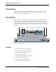
PS9600 Power Supply User Guide Introduction This manual describes the field installation of a Multi-Tech PS9600 power supply into a CommPlete Communications Server CC9600 chassis. Installation and troubleshooting of the PS9600 should be performed only by qualified service personnel. Description The PS9600 is a universal input switching power supply for the CommPlete Communications Server. Two PS9600 power supplies are installed as standard equipment in each CommPlete CC9600 chassis.
1 Introduction Technical Specifications Input voltage 100 VAC to 240 VAC RMS Input frequency 50/60 Hz Input current 8 A @ 115 V at full load 4 A @ 230 V at full load Output voltage at maximum current 5 VDC @ 65 A 21 VDC @ 0.5 A 5 V regulation ± 0.
2 CommPlete Communications Server Installation 5
PS9600 Power Supply User Guide Introduction This chapter describes how to install the PS9600 power supply into a CommPlete Communication Server CC9600 chassis. This equipment should be installed only by a qualified service person. Pre-Installation Notes • All installation must be done by a qualified service person.
3 CommPlete Communications Server Operation 7
PS9600 Power Supply User Guide Introduction This chapter provides information about operating your PS9600 Power Supply after it is installed. Power Switch The PS9600 has a power switch on the front panel that is labeled with the international I (on) and O (off) symbols. For the most reliable operation, both power supplies should be turned on whenever the CommPlete Communications Server is operating. Power Indicator The power indicator lights if all outputs are good.
4 CommPlete Communications Server Solving Problems 9
PS9600 Power Supply User Guide Introduction This chapter provides information needed to identify and fix problems with the PS9600 power supply module. Problems can be observed on the CommPlete system’s front panel LEDs, the control PC’s screen, or via audio alarm or alarm report. In addition, problems can be found when performing the Diagnostic Tests documented elsewhere in the CommPlete Communications Server User Guide.
4 Solving Problems Procedure 1. Turn off the power supply that is not being adjusted. 2. Place your voltmeter’s probes on the test points. 3. Two trimpots, one for each power supply, are located on the back of the chassis between the power supply fans. Adjust the 5 volt trimpot that is closest to the power supply that you are testing to 5.1 VDC by turning it clockwise to increase the voltage, or counterclockwise to decrease the voltage. 4. Check the measurement. 5.
PS9600 Power Supply User Guide Insertion and Removal of a Power Supply Qualified service personnel may insert or remove a power supply without turning off the system. We recommend that you insert the power supply slowly. If the power supply is not replaced, a cover plate must be installed. Safety Disconnect Device The switches on the power supplies are not safety disconnect devices. To reduce the risk of electric shock, unplug the two input power cords from the back of the CC9600.
Index —A— adjusting the output, 11 —M— manual organization, 3 Multi-Tech BBS, 16 —B— —O— BBS, Multi-Tech, 16 operating the PS9600, 8 —C— CC9600 chassis, 6 CompuServe, 17 —D— —P— power bus, 2 power cords, 12 power indicator, 6, 8, 10 power switch, 8 description, 2 dimensions of PS9600, 3 —S— —F— fax-back service, 18 features, 2 fuse, 3, 10 safety, 6, 12 service, 14 solving problems, 10 specifications, 3 switchover time, 2, 8 —T— —I— installation, 6 Internet, 2, 18 —L— technical specifications,
PS9600 Power Supply User Guide 14 CommPlete Communications Server