MultiModem® II Data/Fax Modem MT5600BA-V92 User Guide
Copyright and Technical Support MultiModem II User Guide MT5600BA–V92 PN S000408C Copyright All rights reserved. This publication may not be reproduced. Copyright © 2006-9 by Multi-Tech Systems, Inc. Multi-Tech Systems, Inc. makes no representations or warranties with respect to the contents hereof and specifically disclaims any implied warranties of merchantability or fitness for any particular purpose. Furthermore, Multi-Tech Systems, Inc.
Table of Contents Table of Contents Chapter 1 – Product Description and Features ......................................................................................... 4 Product Description .................................................................................................................................................... 4 Features ..............................................................................................................................................................
Chapter 1 – Product Description and Features Chapter 1 – Product Description and Features Product Description This modem supports two-wire and/or four-wire leased lines. The four-wire leased line includes the dial backup and automatic leased line restoration features. The MultiModem II offers interactive automatic dialing. You can store four command lines or telephone numbers in the modem’s nonvolatile memory.
Chapter 1 – Product Description and Features Safety Warnings • Use this product only with UL- and CUL-listed computers. • To reduce the risk of fire, use only 26 AWG or larger telephone wiring. • Never install telephone wiring during a lightning storm. • Never install a telephone jack in a wet location unless the jack is specifically designed for wet locations. • Never touch uninsulated telephone wires or terminals unless the telephone line has been disconnected at the network interface.
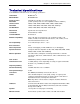
Chapter 1 – Product Description and Features Technical Specifications Your MultiModem II modem meets the following specifications: Trade Name MultiModem® II Model Number MT5600BA-V92 Server-to-Client Data Rates V.92/56K speeds when accessing a V.
Chapter 1 – Product Description and Features Operating Temperature * 32°–120° F (0°–50° C) ambient under closed conditions UL Listed at 40°C Humidity Range 25–85% (non-condensing) Storage Temperature 14°– 185° F (-10° to +85° C) Power Requirement 9 to 12Vdc @ 650mA Power Supply Requirement: Listed ITE power supply, marked “LPS” or “Class II”, output rated: 9 to 12Vdc, 650mA Dimensions 6.2" wide × 1.4” high x 9.0" deep (15.8 cm × 3.6 cm x 22.9 cm) Weight 2 lbs. (0.
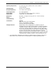
Chapter 2 – Installation Chapter 2 - Installation Step 1 - Connect the Modem to Your System Turn off your computer. Placing the modem in a convenient location, connect it to your computer’s serial port, to the telephone line, to your leased line, to AC power, and, optionally, to your telephone. PHONE LINE LEASED MultiModem II Connections Connect the Modem to Your PC Plug one end of the serial cable into the modem’s RS-232 connector.
Chapter 2 – Installation Connect the Phone to the Modem (Optional) For voice-only calls, plug a telephone into the modem’s PHONE jack. Connect the Modem to the AC Power Outlet Plug the power transformer into an AC power outlet or power strip. Plug the power transformer’s cable into the POWER jack on the modem. Note: Use only the power transformer supplied with the modem. Use of any other transformer voids the warranty and can damage the modem.
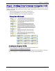
Chapter 2 – Installation Step 3 - Setting Your Country or Region Code The MT5600BA-V92 modem is a global modem - it can be used all over the world. However, countries or regions vary in their requirements for how a modem functions. Therefore, you must configure yours to match the defaults of the country or region in which you are using it.
Chapter 2 – Installation Using the Global Wizard The Global Wizard configuration utility is recommended for computers running in Windows. The Wizard can configure your modem for a specific country or region with just a few mouse clicks. 1. Insert the MultiModem II CD into the CD-ROM drive. The Autorun dialog box appears. 2. Click Initial Setup and Country or Region Selection. The Global Wizard dialog box appears. Click Next. 3. The Global Wizard searches for your modem and identifies it.
Chapter 2 – Installation Step 4 - Install PhoneTools Note: PhoneTools may or may not be included on the MultiModem II CD according to your company's preference. Data communications software gives you access to commands that govern how the modem operates; that is, how the modem handles incoming and outgoing data streams, etc. Multi-Tech includes a data communications software package (PhoneTools) on the product CD shipped with your modem.
Chapter 3 – Using the Front Panel Chapter 3 - Using the Front Panel Like any modem, your Multi-Tech modem operates only under the control of a communication program, such as the PhoneTools program included with the modem. It also operates under other general-purpose data communication programs, such as Windows Terminal and HyperTerminal. For information on how to use the modem with the communication program of your choice, please refer to the program’s documentation.
Chapter 3 – Using the Front Panel Liquid Crystal Display (LCD) The modem’s backlit liquid crystal display (LCD) has two functions: to display the current status of the modem and to display configuration menus, which are selected using the four push buttons on the front panel. Option Selection To select most configuration options, simply display the option in the LCD, and then press the Enter button to select it. An OPTION SET message appears to confirm the selection.
Chapter 3 – Using the Front Panel Status “Trunk” The Status Trunk shows the current operating status of the modem. Limb changes are automatic, but certain options can be accessed by pressing the Æ button. Note that when the modem is online, pressing the Æ button shows the connect status, including the data speed, connection type, and compression type. Multi-Tech Systems, Inc.
Chapter 3 – Using the Front Panel Basic Options “Trunk” Use the Basic Options Trunk to configure the modem’s basic operating conditions. When entering a number, use the arrow buttons to scroll through a list of digits and characters. To go to the next position, press the Æ button. To back up or to exit without dialing, press the Æ button several times. Continued on next page Multi-Tech Systems, Inc.
Chapter 3 – Using the Front Panel Basic Options “Trunk” Continued Multi-Tech Systems, Inc.
Chapter 3 – Using the Front Panel Advanced Options “Trunk” Use the Advanced Options Trunk to configure RS-232, dial backup, and callback security options. When entering a number or password, use the arrow buttons to select a character or digit. To go to the next position, press the Æ button. To backspace or to exit, press the Æ button several times. Note: New LED for Linux (&C6) Available Here Advanced Options Continued on Next Page Multi-Tech Systems, Inc.
Chapter 3 – Using the Front Panel Advanced Options “Trunk” Continued Remote Configuration Options “Trunk” Use the Remote Configuration Options Trunk to enable or disable remote configuration on the modem, and to change the password. When entering the password, use the arrow buttons to scroll through the alphabet. To go to the next character position, press the Æ button. To backspace or to exit, press the Æ button several times.
Chapter 3 – Using the Front Panel Phone Number Memory Options Trunk The MultiModem II can store up to four telephone numbers for speed dialing. Use the Phone Number Memory Options Trunk to store, list, and dial these numbers. When entering a number, use the arrow buttons to scroll through the available digits and dialing commands. To go to the next position, press the Æ button. To backspace or to exit, press the Æ button several times.
Chapter 3 – Using the Front Panel Setting Country/Region Codes Trunk Status 1. Start at the Status LCD and use the down arrow to move down the menu tree to the Region Select LCD. Basic Options 2. Use the right arrow to move from the Region Select LCD, across the Region Setting Options LCD, to the Current Setting LCD. Advanced Options Diagnostics 3. If the current setting shown is not the one for your region, arrow across to the Region Profile LCD.
Chapter 3 – Using the Front Panel Functionality of Menu Options This section describes important LCD options. Many, but by no means all, of the options have AT command equivalents. Status Status LCDs display the current status of the modem. Though limb changes are automatic, certain options can be selected by pressing the Æ button. STATUS = IDLE The modem is ready but inactive. This LCD appears when the modem is first turned on, and is the starting point for accessing all other LCDs.
Chapter 3 – Using the Front Panel Basic Options The following LCDs are used to configure the modem’s basic operating conditions. ONLINE OPTIONS The following LCDs are used to configure the online operation of the modem: LINE TYPE OPTIONS Use the Æ and Enter buttons to select from the following line types: dial-up (PSTN), two-wire leased line originate or answer, and four-wire leased line originate or answer.
Chapter 3 – Using the Front Panel COMMAND MODE OPTIONS The following LCDs are used to configure result code responses. ENABLE/DISABLE RESPONSE Use the Æ and Enter buttons to enable or disable the sending of result codes to the computer. Same as the Q0 and Q1 commands. VERBOSE/TERSE RESPONSE Use the Æ and Enter buttons to select verbose or terse result codes. Same as the V0 and V1 commands. ENABLE/DISABLE CMD MODE Use the Æ and Enter buttons to enable or disable the modem’s ability to accept AT commands.
Chapter 3 – Using the Front Panel Advanced Options RS232 OPTIONS The following LCDs are used to configure the RS-232 interface. DTR OPTIONS Use the Æ and Enter buttons to select how the modem responds to the high to low transition of the DTR signal sent by the computer. DTR NORMAL causes the modem to hang up; IGNORE DTR allows operation with computers that do not provide DTR; and RESET ON DTR È causes the modem to perform a soft reset as if the Z command were received.
Chapter 3 – Using the Front Panel CALLBACK SECURITY Use the Æ and Enter buttons to turn callback security on or off. Same as the #DB0 and #DB1 commands. For more information about callback security, see Chapter 6, “Callback Security.” PASSWORD SETUP Use to enter callback security passwords in memory locations 1–30. Each password must be six to ten characters in length. To scroll through a list of digits and characters, press the Ç Å and È buttons. To go to the next position, press the Æ button.
Chapter 3 – Using the Front Panel Remote Configuration Options The following LCDs are used to configure remote configuration options. For more information about remote configuration, see Chapter 5, “Remote Configuration.” ENABLE/DISABLE R.C Use the Æ and Enter buttons to turn remote configuration on or off. REMOTE CONFIG. PASSWORD Use to enter the remote configuration password. To scroll through a list of digits and characters, press the Ç Å and È buttons. To go to the next position, press the Æ button.
Chapter 3 – Using the Front Panel Caller ID Options Press the Æ and Enter buttons to enable formatted (FCID) or unformatted (UCID) Caller ID or to disable Caller ID altogether. Same as the +VCID=0, +VCID=1, and +VCID=2 commands. Note: Because Caller ID information is sent between the first and second ring, register S0 must be set to 2 or more rings for the modem to receive Caller ID information. Region Select Options Note: See page 10. Multi-Tech Systems, Inc.
Chapter 4 – Leased Line Operation Chapter 4 - Leased Line Operation This chapter describes how to use the MultiModem II modem on a leased line. A leased line is a private, permanent, telephone connection between two points. Unlike normal dialup connections, a leased line is always active. The modems automatically connect when they are attached to the line and are turned on.
Chapter 4 – Leased Line Operation Four-Wire Setup 1. For four-wire leased line operation, connect one end of the four-wire cable to the LEASED jack on the back of the modem. Connect the other end of the cable to a four-wire leased line jack or terminals. 2. Turn on the modem. 3. Starting at the STATUS LCD, press the following buttons on the front panel: È, Æ, È, È, È, Æ, Æ, Æ, Æ. The SYNC, NORM? LCD appears. 4. Press the Enter button to select normal synchronous operation. 5. The OPTION SET LCD appears.
Chapter 4 – Leased Line Operation Dial Backup and Leased Line Restore Setup 1. Connect a telephone cable to the LINE jack of an MT5600BA-V92 modem set up for leased line operation. Connect the other end of the cable to a standard dialup line jack. 2. Turn on the modem. 3. Starting at the STATUS LCD, press the following buttons on the front panel: È, È, Æ, È, Æ, Æ, Æ. The ENTER NUMBER LCD appears. 4. Press the ÇÅ or È button several times to select the first digit in the dial backup telephone number. 5.
Chapter 5 – Remote Configuration Chapter 5 - Remote Configuration Remote configuration is a network management tool that allows you to configure modems anywhere in your network from one location. With password-protected remote configuration, you can issue AT commands to a remote MultiModem II modem for maintenance or troubleshooting as if you were on-site. Basic Procedure The following steps are valid regardless of whether the connection is established by the local or the remote MultiModem II modem. 1.
Chapter 5 – Remote Configuration Changing the Remote Escape Character To improve security, you can change a remote modem’s remote configuration escape character. The remote configuration escape character is stored in register S13. The factory default is 42, which is the ASCII code for the asterisk character (*). Setting S13 to 0 (zero) disables remote configuration entirely— but if you do this remotely, you won’t be able to change it back remotely! 1.
Chapter 6 – Callback Security Chapter 6 - Callback Security This chapter describes how to use callback security with your modem. Callback security protects your network from unauthorized access and helps control long distance costs. When callback security is enabled, all callers are requested to enter a password. If the password is invalid, the caller can try twice more before the modem hangs up.
Chapter 6 – Callback Security Front Panel Method 1. Turn on the modem. 2. Starting at the STATUS LCD, press the following buttons on the front panel to turn callback security on and off: • To turn on callback security, press È, È, Æ, È, È, Æ, Æ to display the CALLBACK ON? option, and then press the Enter button to select the option. When remote callback security is turned on, each caller is asked to enter a password, then is disconnected and called back by the modem.
Chapter 6 – Callback Security Assigning Callback Phone Numbers AT Command Method 1. Open a data communication program, such as HyperTerminal. 2. To store a callback phone number in the first memory location, type AT#CBN01=xxxxxxxxxx, where xxxxxxxxxx is the dialing string, and press ENTER. The dialing string can include the digits 0 through 9 and any of the following characters: #, *, comma (,), semicolon (;), W, A, B, C, and D. Up to 30 characters can be used. Example: AT#CBN01=9,16127853000.
Chapter 6 – Callback Security Calling Procedure Use the following procedure to call a modem that has callback security enabled. Autoanswer must be enabled on the calling modem (S0=1 or S0=2). 1. Using a data communication program such as HyperTerminal, dial the number of the callback modem. 2. When the connection is established, the callback modem responds with a request for a password. 3. Type the password for your modem, and then press ENTER.
Chapter 6 – Callback Security Callback Security Commands The following AT commands are used with callback security. Command: Values: Default: Description: #DBn #DB0 #DB1 Command: Values: #CBNy=[-]x Default: Description: Command: Values: Defaults: Description: #CBPy=x Callback Enable/Disable n = 0 or 1 0 Enables or disables callback security.
Chapter 7 – Troubleshooting Chapter 7 - Troubleshooting Your modem was thoroughly tested at the factory before it was shipped. If you are unable to make a successful connection, or if you experience data loss or garbled characters during your connection, it is possible that the modem is defective. However, it is more likely that the source of your problem lies elsewhere. The following symptoms are typical of problems you might encounter: • None of the LEDs light when the modem is on.
Chapter 7 – Troubleshooting The Modem Does Not Respond to Commands • Make sure the modem is plugged in and turned on. (See “None of the Indicators Light.”) • Make sure you are issuing the modem commands from data communication software, either manually in terminal mode or automatically by configuring the software. • Make sure you are in terminal mode in your data communication program, then type AT and press ENTER.
Chapter 7 – Troubleshooting If you hear a dial tone, your modem might be installed behind a corporate phone system (PBX) with an internal dial tone that sounds different from the normal dial tone. In that case, the modem might not recognize the dial tone and might treat it as an error.
Chapter 7 – Troubleshooting File Transfer Is Slower Than It Should Be • You might have an older UART. For best throughput, install a 16550AFN UART or a Multi-Tech ISI serial port card. • If you are using a slow transfer protocol, such as Xmodem, try Zmodem or Ymodem/G instead. • Is your line noisy? If there is static on your line, the modem has to resend many blocks of data to insure accuracy. You must have a clean line for maximum speed.
Appendix A – Regulatory Compliance Appendix A - Regulatory Compliance FCC Part 68 Telecom 1. This equipment complies with part 68 of the Federal Communications Commission Rules. On the outside surface of this equipment is a label that contains, among other information, the FCC registration number. This information must be provided to the telephone company. 2. The suitable USOC jack (Universal Service Order Code connecting arrangement) for this equipment is shown below.
Appendix A – Regulatory Compliance Canadian Limitations Notice Notice: The ringer equivalence number (REN) assigned to each terminal device provides an indication of the maximum number of terminals allowed to be connected to a telephone interface. The termination on an interface may consist of any combination of devices subject only to the requirement that the sum of the ringer equivalence numbers of all the devices does not exceed 5. Notice: The Industry Canada label identifies certificated equipment.
Appendix A – Regulatory Compliance New Zealand Telecom Warning Notice 1. The grant of a Telepermit for any item of terminal equipment indicates only that Telecom has accepted that the item complies with minimum conditions for connection to its network. It indicates no endorsement of the product by Telecom, nor does it provide any sort of warranty.
Appendix B – Upgrading the Firmware Appendix B - Upgrading the Firmware Introduction Your modem is controlled by semi-permanent software, called firmware, which is stored in flash memory. Firmware is nonvolatile; that is, it remains stored in memory when the modem is turned off. However, it can be changed by either the manufacturer or the user as bugs are fixed or new features are added.
Appendix B – Upgrading the Firmware 5. If the firmware version number is greater than the firmware version number found in “Step 1: Identify the Modem Firmware,” your modem has an older firmware version. Continue with “Step 3: Download the Upgrade File.” Warning: The first digit of the new firmware must match the first digit of the old firmware, or the modem may not work properly; e.g., if your current firmware version is 4.16, replace it only with 4.xx firmware, not 6.xx firmware.
Appendix B – Upgrading the Firmware Caution: Any disruption of the program during this stage of the upgrade can cause your modem to become inoperable. Wait for the Next button to become active before proceeding. 5. When the flash upgrade is complete, the message Programming Complete appears. Click Next to continue. 6. The Results dialog box appears next. Click Finish to exit Flash Wizard. Step 7 - Restore Your Parameters Your modem has been updated.
Appendix C – Installing a Modem Under Linux Appendix C - Installing a Modem Under Linux Introduction This appendix explains how to install a modem on a computer operating under the Red Hat Linux 6.2 operating system. Other versions of Red Hat and other Linux operating systems should be similar. Briefly, in Linux, you do not need drivers for most standard external modems and most internal ISA bus modems. Programs in Linux commonly call upon the port, rather than the modem.
Appendix C – Installing a Modem Under Linux Calling the ISP 1. 2. 3. 4. 5. On the Task Bar at the bottom of the LCD, select the Gnome Footprint. Select Internet from the menu. Select RH PPP Dialer. Select the connection name you entered in step 5 of the previous section. Click OK. Answering Calls To use the system for answering calls, Linux requires other programs to be installed, such as Mgetty, Mgetty+Sendfax, and others, depending on your requirements.
Appendix D – Pin Descriptions Appendix D - Pin Descriptions RS-232 Pin Descriptions Label CGND TD Pin 1 2 RD 3 RTS CTS 4 5 DSR 6 I/O Type GND Signal Name/Description CGND is tied common to GND on the modem’s PCB. Transmitted Data The DTE uses the TD line to send data to the modem for transmission over the telephone line or to transmit commands to the modem. Received Data The modem uses the RD line to send data received from the telephone line to the DTE and to send modem responses to the DTE.
Appendix D – Pin Descriptions RS-232 Cable Pinouts 25-Pin to 25-Pin RS-232 Cable 9-Pin to 25-Pin RS-232 Cable Leased Line Pinouts Two-Wire Leased-Line Cable 2345 3 4 2 5 Red Transmit Pair Green Yellow Receive Pair Black RJ-11 Modular Plug To Terminal Block Screws Four-Wire Leased-Line Cable Multi-Tech Systems, Inc.
Appendix E – WEEE Statement Appendix E – Waste Electrical and Electronic Equipment Statement WEEE Directive The WEEE directive places an obligation on EU-based manufacturers, distributors, retailers, and importers to take-back electronics products at the end of their useful life. A sister Directive, ROHS (Restriction of Hazardous Substances) complements the WEEE Directive by banning the presence of specific hazardous substances in the products at the design phase.
Appendix F – ROHS HT/TS Substance Concentration Appendix F – ROHS HT/TS Substance Concentration 依照中国标准的有毒有害物质信息 根据中华人民共和国信息产业部 (MII) 制定的电子信息产品 (EIP) 标准-中华人民共和国《电子信息产品污染控制管理办法》(第 39 号),也称作中国 RoHS,下表列出了 Multi-Tech Systems Inc.
Index Index A advanced menu options ........................................... 25 Advanced Options Trunk .......................................... 18 analog loopback test ................................................ 27 AT commands #CBN= ........................................................... 26, 38 #CBP=...................................................... 26, 27, 38 #CID= ................................................................... 28 #DB .................................................
Index modem reset menu option ......................................................... 16 Monitor Options menu .............................................. 26 P phone connection ....................................................... 8 phone number memory options.......................... 20, 27 Phone Number Memory Options Trunk.................... 20 Pinouts for Leased Line ........................................... 52 Pinouts for RS-232 Cable ........................................ 52 protocols ....