
User manual


Chapter 3 - Installation
29
3.3 Installation
The installation procedure describes how to connect the RouteFinder
100
to an Ethernet LAN, a terminal or PC
for configuration and a WAN.
Installation Procedure
Step Procedure
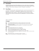
1 Connect the external power supply to the RouteFinder
100
and a live AC outlet. The POWER connector on
the back panel of the RouteFinder
100
is a 6-pin circular DIN connector.
Figure 3-2. Power Connection
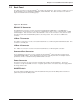
2 Connect a PC running Windows® to the COMMAND PORT connector on the back panel of the
RouteFinder
100
. Use the short RJ45 to DB25 cable provided with the RouteFinder
100
to connect to the PC.
Figure 3-3. PC to Command Port
3 Configure the RouteFinder
100
for your application using the procedures in Chapter 4.
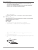
4 Connect a network cable to either the ETHERNET 10BASE-T (RJ45) or coax cable to the BNC connector
on the back panel of the RouteFinder
100
. Connect the other end of the cable to the network.
Figure 3-4. Network Connection