Model MTA128ST-USB External ISDN Terminal Adapter User Guide
User Guide Model MTA128ST-USB P/N 88311700 Revision A Copyright ©1999, by Multi-Tech Systems, Inc. All rights reserved. This publication may not be reproduced, in whole or in part, without prior expressed written permission from Multi-Tech Systems, Inc. Multi-Tech Systems, Inc. makes no representations or warranties with respect to the contents hereof and specifically disclaims any implied warranties of merchantability or fitness for any particular purpose. Furthermore, Multi-Tech Systems, Inc.
Contents Chapter 1 - Introduction and Description Introduction ................................................................................................................................................ Product Description .................................................................................................................................... Universal Serial Bus (USB) ........................................................................................................................
Displaying a Stored Number .............................................................................................................. Answering a Call ...................................................................................................................................... Answering Manually ........................................................................................................................... Answering Automatically .......................................................
Chapter 1 - Introduction and Description
MultiModemISDN User Guide Introduction Welcome to the world of data communications. You have acquired one of the finest ISDN terminal adapters (TA) available today from one of America’s oldest and most respected modem manufacturers: Multi-Tech Systems, Inc. This user guide will help you install, configure, test and use your terminal adapter.
Chapter 1 - Introduction and Description Manual Organization This manual is divided into six chapters and two appendixes: Chapter 1: Introduction and Description—Summarizes product features, lists technical specifications, and provides an overview of manual’s organization. Chapter 2: Installation—Describes how to connect the MTA128ST-USB to the computer, to power, to the ISDN BRI line, and to an optional analog device. It also describes the functions of the front panel LED indicators.
MultiModemISDN User Guide Features The MTA128ST-USB communicates over public ISDN telephone lines. Features include: 8 • Compatibility with EuroISDN (ETSI/DSS1/NET3), French VN4, and Japanese INS64 switch protocols • USB interface for easy installation; hot-swappable (Windows 98) with other USB devices without restarting or reconfiguring your PC • Compatibility with U.S. NI-1, AT&T 5ESS, and DMS-100 switch protocols • Compatibility with V.110, V.120, ML-PPP, and X.
Chapter 1 - Introduction and Description Technical Specifications Your MTA128ST-USB terminal adapter meets the following specifications: MTA128ST-USB Trade Name MultiModemISDN Model Number MTA128ST-USB (International) Network Interface Four-wire S/T interface Switch Compatibility EuroISDN (ETSI/DSS1/NET3), VN4, INS64, U.S. NI-1, AT&T 5ESS, DMS-100 B-Channel Protocols V.110, V.120, X.
MultiModemISDN User Guide 10 MTA128ST-USB
Chapter 2 - Hardware Installation
MultiModemISDN User Guide Introduction This chapter details the contents of the MTA128ST-USB shipping container, describes each cable connection, and describes the LED indicators. Unpacking Your MTA128ST-USB The shipping box contains the MTA128ST-USB, an external power supply, one RJ-45 line cord, one RJ-11 phone cord, one USB cable, your Quick Start Guide, and two diskettes (i.e., the MTA128ST-USB User Guide and the MTA128ST-USB Driver Software). Inspect the contents for signs of any shipping damage.
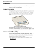
Chapter 2 - Hardware Installation Assembling the MTA128ST-USB The only assembly required is to mount the feet on the bottom of your unit (See Figure 22). Peel the four self-adhesive plastic feet off the backing strip and press them into the recesses on the bottom. TD RD LS B1 B2 TR OH 128 P1 P2 USB ISDN Modem with Analog Port Figure 2-2. Mounting the Feet Connecting the MTA128ST-USB to Your System Place the MTA128ST-USB terminal adapter in a convenient location.
MultiModemISDN User Guide Connecting to Your Computer 1. Plug the 4-pin flat end (Type A) into a USB port connector on your computer or laptop. Note: Do NOT plug the D-shaped end (Type B) of the USB cable into the USB connector on the back panel of the MTA128ST-USB at this time. You will make the connection at Step 2 when installing the software drivers. Connecting to Power 1. Plug the power supply into the unit’s POWER connector. 2. Plug the power supply into a live AC outlet. 3.
Chapter 2 - Hardware Installation LED Indicators The ten LED indicators on the front panel (see Figure 2-4) of the MTA128ST-USB report status and line activity. USB ISDN Modem with Analog Port TD RD LS B1 B2 TR OH 128 P1 P2 Figure 2-4: Front Panel TD Transmit Data Flashes when data is being transmitted (on for a space, off for a mark). RD Receive Data Flashes when data is being received (on for a space, off for a mark). LS Power Lights when the unit is turned on.
MultiModemISDN User Guide P1 Data Protocol Lights in combination with P2 and 128 LEDs to indicate which data protocol (V.110, V.120, X.75, PPP, MLPPP) is in use as shown in the table below. P2 Data Protocol Lights in combination with P1 and 128 LEDs to indicate which data protocol (V.110, V.120, X.75, PPP, MLPPP) is in use as shown below: Data Protocol 128 LED P1 LED P2 LED V.110 V.120 X.
Chapter 3 - Software Installation and Configuration
MultiModemISDN User Guide Introduction This chapter describes how to install the MTA128ST-USB driver software and discusses how to configure the unit to match your ISDN service and remote terminal adapter (TA). Driver Software Installation MTA128ST-USB driver software is installed in Win 98 or Win 95 operating environments. Installing in Windows 98 1. Power up your Windows 98 system. 2. Turn on your MTA128ST-USB. The LS (Power) LED will light. 3.
Chapter 3 - Software Installation and Configuration 6. The Add New Hardware Wizard dialog box is displayed. Verify that the “Floppy disk drives” option is selected and click Next >. 7. The Add New Hardware Wizard dialog box is displayed. Windows will select the proper driver from the installation disk and will display the information for verification. Click Next > to install the selected driver. 8. Windows proceeds to copy the files to the system and then displays the Add New Hardware Wizard dialog box.
MultiModemISDN User Guide Note: Click My Computer | Properties | Device Manager to see if driver software was installed. Modem Installation After the driver software has been installed, you will need to install the appropriate modems. These are included on the driver disk shipped with your MTA128ST-USB. 1. Click Start | Settings | Control panel | Modems. 2. The Modems Properties dialog box is displayed. 3. From the General tab, click the Add button. 4. The Install New Modem dialog box is displayed.
Chapter 3 - Software Installation and Configuration Removing Your Old Device from Windows 98/95 When your new MTA128ST-USB replaces another terminal adapter, the old installation remains in Windows 98/95 after you install the new device, and the old device is still selected in HyperTerminal and other Windows 98/95 applications.
MultiModemISDN User Guide Network Configuration Network Switch Type _____________________________ Select the network switch type your ISDN service provider uses at its local central office. You can set the MTA128ST-USB to NET3 (DSS1), VN4, INS64, U.S. NI-1, AT&T 5ESS, or DMS-100. If you don’t know the switch type, get the information from your ISDN service provider.
Chapter 3 - Software Installation and Configuration Call Control Configuration Persistent DTR Dialing _______________________ A high DTR (Data Terminal Ready) signal on the USB port indicates your computer or terminal is ready to communicate with your MTA128ST-USB. DTR normally goes high when a communication program starts or is ready to dial.
MultiModemISDN User Guide ISDN MTA128ST-USB Configuration Utility Use the ISDN MTA128ST-USB Configuration Utility with computers running Windows 98/ 95 operating systems only. Because it is a software utility, you can use it to create and store as many different configurations as you wish. To Install in Windows 98/95 1. When installing from disk, insert the Setup disk (provided in your MTA128ST-USB package) into drive A or B. If installing from a network location, connect to it. (Note the drive letter.
Chapter 3 - Software Installation and Configuration Windows 98/95 Dial-Up Networking Windows 98/95 includes a remote-node client called Dial-Up Networking (DUN). To install and operate Dial-Up Networking 1. Insert the Windows 98/95 CD-ROM into the CD ROM drive. 2. In Windows 98/95, click Start | Settings | Control Panel | Add/Remove Programs. 3. Click the Windows Setup tab. 4. In the Components list, select Communications; then click Details. 5.
MultiModemISDN User Guide 26 MTA128ST-USB
Chapter 4 - AT Commands, S-Registers and Result Codes
MultiModemISDN User Guide Introduction One of the ways you can communicate with and configure your MTA128ST-USB is to use AT commands. AT commands are so-called because, with only a few exceptions, each command string begins with the characters AT. Using AT commands, you can read and set parameters, and perform actions such as dialing. Note: For purposes of brevity, the MTA128ST-USB is referred to as the TA (terminal adapter) throughout this chapter.
Chapter 4 - AT Commands, S-Registers and Result Codes AT Commands by Function Command Implementation AT Return +++AT AT Switch %A97 !C0 !C6 *!C6 !D3 *!D3 !L >Dn !N1 !N2 *!N1 !RXG !TXG !Z=n Attention code Command execution In-band escape code Out-of-band escape code Configuration Dialing method Switch type Data SPID Voice SPID SAPI-0 data TEI SAPI-0 voice TEI List DN, SPID, TEI, Data protocol & switch type Embedded Protocol Analyzer Data DN/MSN 1 Data DN/MSN 2 Voice DN/MSN Receive gain Tran
MultiModemISDN User Guide Data Call Commands A Answer D Dial DSn Dial Stored telephone number &Jn H In On @Config Channel Bundling Hang up Display product information Return on-line Start ConfigMenu Command Implementation Command: AT Function: Attention Code Values: n/a Default: n/a Description:The attention code precedes all command strings except the A/ command and escape codes. Command: RETURN Function: Command Execution Default: n/a Values: n/a Description:Press RETURN (ENTER) to execute a command.
Chapter 4 - AT Commands, S-Registers and Result Codes Switch Configuration Commands Use the following commands to select your network switch type (e.g., EuroISDN Net3) and to specify other information required to make an ISDN connection. Command: %A97=n Function: Dialing Method Values: n = 0 or 1 Default: %A97=0 (En bloc) Description:Standardized ISDN signaling protocols such as DSS1, DSS2, and SS7 support sending complete indication, (a signal that no more digits follow).
MultiModemISDN User Guide Command: !D3=n Function: SAPI-0 Data TEI Values: n = 0–63, 240 (auto), 241 (disable) Default: !D3=240 (Auto TEI) Description:Use !D3= to set the terminal endpoint identifier (TEI) for the data channel. A TEI is a number used by the central office switch to identify uniquely each device connected to the network. When it uses dynamic TEI assignments (auto TEI), the central office switch assigns a TEI each time the TA connects to the network.
Chapter 4 - AT Commands, S-Registers and Result Codes Command: !N1=n Function: Data DN/MSN 1 Values: n = 25 character string Default: null string Description:!N1 sets the Directory Number (DN)/Multiple Subscriber Number (MSN) for the data channel. The DN/MSN is a telephone number assigned to the TA at subscription time by the ISDN service provider. The DN/MSN is a string of up to 25 characters; valid characters are 0–9, the * character, and the # character.
MultiModemISDN User Guide Command: !Z=n Function: Rate Adaption Protocol Values: n = 5, 6, 9, or 12 Default: !Z=9 (ML-PPP) Description:Selects rate adaption protocol used to communicate with another TA. The local and remote terminal adapters must be set to the same protocol for communication to take place. !Z=5 V.120 protocol !Z=6 V.110 protocol !Z=9 ML-PPP protocol !Z=12 X.
Chapter 4 - AT Commands, S-Registers and Result Codes Command: Sr=n Function: Set Register Value Values: r = S-register number; n varies Default: None Description:Use Sr=n to set value of an S-register, where r is the number of the Sregister, and n is the value you want to set. See S-Registers in this chapter for more information.
MultiModemISDN User Guide Note that whereas the &F0 reset command always restores the factory default profile, the Z reset command restores either the factory default or the stored profile, depending on how the &W command is set. Command: &Cn Function: DCD Control Values: n = 0, 1, or 2 Default: &C1 (DCD normal) Description:Controls behavior of the DCD (Data Carrier Detect) signal (pin 8 on the RS232E/V.24 interface).
Chapter 4 - AT Commands, S-Registers and Result Codes Command: &En Function: Flow Control Values: n = 3–7, 12, 13 Default: &E4, &E6, &E13 Description:Selects method by which the TA controls the flow of data to and from the computer to prevent either device from accepting data faster than it can handle. The TA provides flow control in both directions. When the TA halts data flow, it is called flow control; when the computer halts data flow, it is called pacing.
MultiModemISDN User Guide Command: &Fn Function: Load Quick Setup Profile Values: n = 0–4 Default: &F0 Description:For quick setup, the TA includes six Quick Setup Profiles, each contains configuration parameters for a specific type of port operation. To load a Quick Setup Profile into active memory, use &Fn, where n is the profile number to load. You then can customize the profile and store it using the &W command, so it loads automatically on power-up or reset.
Chapter 4 - AT Commands, S-Registers and Result Codes Command: &Wn Function: Store Active Profile Values: n = 0 or 1 Default: &W1 (Use factory default profile) Description:Stores your active profile, or configuration, in memory, so you won't lose custom settings when you turn off the TA or reset it.
MultiModemISDN User Guide Command: $MBn Function: V.110 Network Rate Values: n = 600, 1200, 2400, 4800, 9600, 19200, 38400 Default: $MB38400 Description:If S77=1, then the network rate of the V.110 connection will match that of $MB (S76). If a V.110 call is received and S77=1, then the incoming V.110 network rate must match $MB (S76) or the connection will fail. If S77=2 and a V.110 call is originated, then the network rate will match that of $MB (S76). If S77=2 and a V.
Chapter 4 - AT Commands, S-Registers and Result Codes Data Call Commands Use these commands to make or configure data calls. Command: A Function: Answer Call Values: none Default: none Description:Forces TA to answer an incoming call. To make the TA autoanswer, set register S0 to a value higher than 0. Command: D Function: Dial Values: none Default: none Description:The D command causes the TA to dial a number (e.g., ATD785-3500 ).
MultiModemISDN User Guide Command: @CONFIG Function: Start ConfigMenu Values: none Default: none Description:The @CONFIG command starts the TA’s internal configuration utility, used to customize the TA’s configuration for your application. You must enter the command while in your communication program’s terminal mode.
Chapter 4 - AT Commands, S-Registers and Result Codes S-Registers S-registers are sections of memory in which values are stored that affect how the MTA128STUSB operates. S-registers are so-called because each has a name that begins with the character S. Use the S command to assign a value or to read the current value of an S-register. To assign a value to an S-register, use the command Sr=n, where r is the register number, and n is the value you want to assign, e.g., S7=45.
MultiModemISDN User Guide S-Register: S0 Function: Number of Rings Until Answer Unit: 1 ring Range: 0–255 Default: 1 Description:Sets the number of rings the TA waits for before it answers and begins its connect sequence. S0=0 turns off the ability to automatically answer a call. S0=1 causes the TA to automatically answer after 1 ring. If the S0 value is set too high, the calling device may time out before the TA answers the call.
Chapter 4 - AT Commands, S-Registers and Result Codes S-Register: S7 Function: Wait for Connection (Abort Timer) Unit: 1 second Range: 0–255 Default: 45 Description:Sets the Abort Timer delay time, which is the length of time the TA waits for a connection after dialing. If no connection is established during the specified time, the TA ends the call.
MultiModemISDN User Guide S-register: Function: Unit: Range: S30 On-line Inactivity Timer 1 minute n=0 Does not disconnect n=1–255 Default: 0 (does not disconnect) Description:Makes the TA disconnect a data connection if no data is transmitted or received for the specified time. It will NOT cause a POTS call (voice/modem/ fax) to disconnect. The timer restarts any time a data character passes through the serial port (either sent or received).
Chapter 4 - AT Commands, S-Registers and Result Codes S-Register: S44 Function: POTS Port Ring Frequency Unit: Decimal ASCII code Range: 2–4 Default: 2 (25 Hz) Description:Controls the ring frequency from the POTS port. S44=n where: n=2 25 Hz ring frequency n=3 20 Hz ring frequency n=4 16.
MultiModemISDN User Guide S-Register: S50 Function: Caller Line ID (CLI) Unit: Decimal ASCII code Range: 0 or 1 Default: 1 (enabled) Description:Sets whether the mechanism for identifying two endpoints of a connection is enabled or disabled. Since RING messages only appear for ISDN data calls, the CLI feature does not define a means of conveying Calling Party information to the terminal for ISDN voice calls.
Chapter 4 - AT Commands, S-Registers and Result Codes S-Register: S53 Function: Maximum X.75 Buffer Size Unit: 1 byte Range: n=64 - 2048 Default: 2048 (bytes) Description:S53 allows the maximum buffer size of an X.75 frame to be customized. Typically a smaller frame size is more compatible with software packages on a PC (such as HyperTerminal). Larger frame sizes introduce larger delay which some software cannot deal with appropriately.
MultiModemISDN User Guide 4 Telex 8 National standard 9 Private Default: 128 (disabled) Description:Modifies the value of Octet 3 of the Calling Party Number Information Element that is sent within the SETUP message for data and POTS port (voice/modem/fax) calls. To set a specific number type and numbering plan, select an option from the Type of Number section above and add its value to the value of an option in the Numbering Plan section above.
Chapter 4 - AT Commands, S-Registers and Result Codes S-register: Function: Unit: Range: S58 Client-side Authentication Protocol Negotiation Decimal ASCII code n=1 PAP n=2 PAP between TA and PC; CHAP MD5 between TA and server n=3 ANY authentication protocol Default: 1 (PAP) Description:Sets the client-side authentication protocol to be negotiated during the Link Control Protocol (LCP) phase of PPP/MLPPP negotiation.
MultiModemISDN User Guide Note: Using the DBA scheme on the host-side requires that you specify a Data Directory Number or MSN. Refer to your TA Owner’s Manual for information on how to specify a Data Directory Number or MSN. S-register: S60 Function: Bandwidth-on-Demand (BOD) High Threshold Sampling Period Unit: Seconds Range: n=0 (BOD completely disabled) n=1 1–255 Default: 10 (10 seconds) Description:Sets the Bandwidth-on-Demand High Threshold Sampling Period.
Chapter 4 - AT Commands, S-Registers and Result Codes S-register: S63 Function: Bandwidth-on-Demand Low Throughput Threshold Unit: Kbps Range: n=0–64 (Kbps) Default: 26 (26 Kbps) Description:Sets BOD Low Throughput Threshold, which determines whether second channel should be disconnected due to low throughput. Refer to the BOD description and how the Low Throughput Threshold (S63) and Low Threshold Sampling Period (S62) determine when second channel should be disconnected.
MultiModemISDN User Guide S-register: Function: Unit: Range: S66 Country Selections for POTS Ring Signal Decimal ASCII code n=0–27 0 Default 1 Custom single 2 Custom dual 3 Austria 4 Belgium 5 Cyprus 6 Denmark 7 Finland 8 France 9 Germany 1 10 Germany 2 11 Greece 12 Iceland 13 Ireland 14 Italy 15 Luxembourg 1 16 Luxembourg 2 17 Malta 18 Netherlands 19 Norway 20 Portugal 21 Spain 22 Sweden 23 Switzerland 1 24 Switzerland 2 25 United Kingdom 1 26 United Kingdom 2 27 United States Default: 0 (25 Hz, single ri
Chapter 4 - AT Commands, S-Registers and Result Codes S-register: S68 Function: First Active Duration Unit: 1 ms Range: 5–9995 Default: 2000 ms Description:Sets the duration of the first active period of the ring signal. Any value given to this S-register is rounded down to the nearest 5 ms. For example, S68=1234 sets S68 to 1230 ms (1.23 seconds).
MultiModemISDN User Guide complete. The PPP Magic-Number Block contains 5 Magic-Numbers in this implementation and is the default type. The Public Switched Network Directory Number option uses Data Directory Number 1 as the Endpoint Discriminator (if it is blank, then Endpoint Discriminator is blank). The Locally Assigned Address (S73=1), IP Address (S73=2), and IEEE 802.
Chapter 4 - AT Commands, S-Registers and Result Codes Auto-synchronizing allows the TA to adapt to the client’s network rate without any need for the host to have its network rate predetermined. If S77=2 and a V.110 call is originated, then the network rate will be that of S76 ($MB).
MultiModemISDN User Guide Using AT Commands to Operate the MTA128ST-USB You can configure and operate the MTA128ST-USB entirely with AT commands if you like. But remember, you can issue AT commands only from a terminal or from a computer running a communications program in terminal mode. This section describes how to use AT commands for basic operations, such as calling, answering a call, and hanging up. Modes of Operation The MTA128ST-USB has three modes of operation.
Chapter 4 - AT Commands, S-Registers and Result Codes Channel Bundling Flag Dialing The command AT&Jn is used to indicate whether outgoing calls should be made on two B-channels by default. The command AT&J1&W0, configures the TA to place a call, dialing on two B-channels by default. If no second number is given in the dial string, that single number is dialed twice. This compensates for the interworking issues with Windows 95.
MultiModemISDN User Guide Answering a Call You can answer incoming calls to the TA either manually or automatically. When the TA detects an incoming call, it sends a RING result code to the computer or terminal after each ring. If autoanswer is enabled, the TA automatically answers the call. You can manually answer the call with the A command. Both methods are described below.
Chapter 5 - Troubleshooting
MultiModemISDN User Guide Introduction This chapter describes basic problems you may run into with your MTA128ST-USB and how to solve them. Your MTA128ST-USB was thoroughly tested at the factory before it was shipped. If you are unable to make a successful connection, or if you experience data loss during your connection, it is possible that the MTA128ST-USB is defective. However, it is more likely that the source of your problem lies elsewhere.
Chapter 5 - Troubleshooting The MTA128ST-USB does not respond to commands • Make sure the MTA128ST-USB is plugged in and turned on. (See None of the LEDs Light When the MTA128ST-USB Is On.) • Try resetting your MTA128ST-USB by turning it off and on. • Make sure you are issuing the MTA128ST-USB commands from the data communications software, either automatically, or manually in terminal mode. (You cannot send commands to the MTA128ST-USB from the DOS prompt.
MultiModemISDN User Guide • The MTA128ST-USB may be defective. If you have another Multi-Tech MTA128STUSB, try swapping units. If the problem goes away, the first MTA128ST-USB is possibly defective. Call Tech Support for assistance (see Chapter 6). The MTA128ST-USB dials but cannot make a connection There may be several reasons the MTA128ST-USB fails to make a connection. Possibilities include • Lack of a proper physical connection to the communication line. • A busy signal. • A wrong number.
Chapter 5 - Troubleshooting You cannot place two simultaneous data calls • You may not have ordered an ISDN line configuration that supports two simultaneous calls. Check your contract or latest statement of service from your ISDN provider. Also, your ISDN provider may have programmed the switch incorrectly. Call the provider. • You may have misconfigured your MTA128ST-USB to dial two simultaneous data calls.
MultiModemISDN User Guide Data is being lost • USB cable is not plugged in. • Make sure the flow control method you selected in software matches the method selected in the MTA128ST-USB. Making a V.120 call, caller gets a NO CARRIER message after dialing the number Some switches don’t support ISDN SETUP messages that contain a LLC (low layer compatibility) element. When these switches receive an LLC in the SETUP, they immediately reject the call and a NO CARRIER message displays. Disable LLC for V.
Chapter 5 - Troubleshooting MTA128ST-USB receives garbage characters when connected to a 3Com Impact IQ terminal adapter Most likely, the Impact IQ has compression turned on. The compression used by the Impact IQ is incompatible with the compression used by the MTA128ST-USB. Disconnect the data connection and give the Impact IQ the command AT%CO and then establish the data connection again. The garbage characters should disappear.
MultiModemISDN User Guide 68 MTA128ST-USB
Chapter 6 - Warranty, Service, and Technical Support
MultiModemISDN User Guide Introduction This chapter begins your MTA128ST-USB’s five-year warranty. If you have questions or problems with your unit carefully read the next section, Technical Support. It includes the technical support telephone numbers and information on how to send in your terminal adapter should you require service.
Chapter 6 - Warranty, Service, and Tech Support Technical Support Multi-Tech has an excellent staff of technical support personnel available to help you get the most out of your Multi-Tech product. If you have any questions about the operation of this unit, call Technical Support at (612) 717-5863. Service If your tech support specialist decides service is required, send the MTA128ST-USB (freight prepaid) to our factory. Return shipping charges are paid by Multi-Tech Systems (within North America).
MultiModemISDN User Guide Downloading a File If you know the file name 1. From the Main Menu, enter F to access the Files Menu. Then enter D. 2. Enter the name of the file you want to download from the BBS. 3. If a password is required, enter the password. 4. Answer Y or N to the automatic logoff question. 5. Select a file transfer protocol by entering the indicated letter, such as Z for Zmodem (the recommended protocol). 6. If you select Zmodem, the transfer begins automatically.
Chapter 6 - Warranty, Service, and Tech Support Upgrading the MTA128ST-USB with FlashWizard The MTA128ST-USB has a flash PROM, which contains firmware code for the hardware. At various times, Multi-Tech may add enhancements and/or fixes to the firmware. The flash technology used in the MTA128ST-USB lets you load these upgrades into the PROM through the MTA128ST-USB’s USB port. Using FlashWizard to Upgrade Firmware 1. Download the Flash Wizard utility and the new .
MultiModemISDN User Guide Ordering Accessories SupplyNet, Inc. supplies replacement transformers, cables and connectors for select Multi-Tech products. You can place an order with SupplyNet via mail, phone, fax or the Internet at: Mail: SupplyNet, Inc. 614 Corporate Way Valley Cottage, NY 10989 Phone: 800 826-0279 Fax: 914 267-2420 Email: info@thesupplynet.com Internet: http://www.thesupplynet.com SupplyNet Online Ordering Instructions 1. Browse to http://www.thesupplynet.com.
Appendixes
MTA128ST-USB User Guide Appendix A: Regulatory Compliance Class B Statement FCC Part 15 This equipment has been tested and found to comply with the limits for a Class B digital device, pursuant to Part 15 of the FCC Rules. These limits are designed to provide reasonable protection against harmful interference in a residential installation.
Appendix B - Configuration Profiles EMC, Safety, and Terminal Directive Compliance The CE mark is affixed to this product to confirm compliance with the following European Community Directives: Council Directive 89/336/EEC of 3 May 1989 on the approximation of the laws of Member States relating to electromagnetic compatibility; and Council Directive 73/23/EEC of 19 February 1973 on the harmonization of the laws of Member States relating to electrical equipment designed for use within certain voltage limit
MTA128ST-USB User Guide Appendix B: Configuration Profiles Quick Setup Factory Profiles For quick setup, the MTA128ST-USB includes six Quick Setup Factory Profiles, each of which is configured for a specific type of port operation. You can load a Quick Setup Factory Profile into active memory by using the command &Fn, in which n is the number of the profile you wish to load.
Appendix B - Configuration Profiles Profile 0 (&F0) — Modem-Like Asynchronous Operation AT COMMAND DESCRIPTION &C1 $D0 &D1 E1 &E4 &E6 &E13 #X0 &J0 %E1 %E4 &R1 S0=1 S2=43 S3=13 S4=10 S5=8 S7=45 S10=20 S25=5 S32=20 S34=2 S50=1 S52=1 S53=2048 &S1 V1 !Z=x MTA128ST-USB DCD functions normally Disable persistent DTR dialing Hang up when DTR drops Enable command mode echo Enable hardware flow control Discard XON/XOFF characters Enable pacing Disable Sending Multiple Xoff Characters Disable Automatic Channel Bun
MTA128ST-USB User Guide Profile 1 (&F1) — V.
Appendix B - Configuration Profiles Profile 2 (&F2) — V.
MTA128ST-USB User Guide Profile 3 (&F3) — X.
Appendix B - Configuration Profiles Profile 4 (&F4) — ML-PPP Asynchronous Operation AT COMMAND DESCRIPTION &C1 $D0 &D1 E1 &E4 &E6 &E13 #X0 &J0 %E1 %E4 &JMh MTA128ST-USB DCD functions normally Disable persistent DTR dialing Hang up when DTR drops Enable command mode echo Enable hardware flow control Discard XON/XOFF characters Enable pacing Disable Sending Multiple Xoff Characters Disable Automatic Channel Bundling Enable +++ escape method No OK response to +++ or escape 83
MTA128ST-USB User Guide 84 MTA128ST-USB
Glossary
MultiModemISDN User Guide Symbol 2B1Q (2 bits, 1 quarternary)—A line code at layer one for the BRI U interface. Two bits of data (2B) are mapped into one of four line values (1Q, or 1quarternary). This coding scheme allows a single copper pair to carry 160 Kbps of information bidirectionally and simultaneously at a distance of up to three miles. A ACK (acknowledgement code)—A communications code sent from a receiving modem to a transmitting modem to indicate that it is ready to accept data.
Glossary buffer—A temporary storage register or random access memory (RAM), used in all aspects of data communications, that prevents data from being lost due to differences in transmission speed. Keyboards, USB ports, muxes and printers are a few examples of devices that contain buffers. bus—A common channel between hardware devices, either internally between components in a computer, or externally between stations in a communications network.
MultiModemISDN User Guide driver—A software module that interfaces between the operating system and a specific hardware device (e.g., color monitors, printers, hard disks, etc.). Also known as a device driver. DTE (data terminating equipment)—A term used to include any device in a network which generates, stores or displays user information. DTE is a telecommunications term that usually refers to PCs, terminals, printers, etc.
Glossary IRQ (interrupt request)—The notification a processor receives when another portion of the computer’s hardware requires its attention. IRQs are numbered so that the device issuing the IRQ can be identified, and so that IRQs can be prioritized. ISA (Industry Standards Architecture)—Pronounced ice-a. The classic 8- or 16-bit architecture introduced with IBM’s PC-AT computer.
MultiModemISDN User Guide O OHCI (OpenHCI): Open Host Controller Interface Specification for USB. All transfers on the USB are initiated by the host system’s host controller. The host controller is responsible for controlling traffic on the USB and can be appropriately programmed to transfer data to and from USB devices. This is typically a PCI device that can be programmed to run a given schedule of transfers on the USB and bus master the results into memory for processing by the host software.
Glossary reference point—A connection point between ISDN equipment classes (rather than the specific protocol of the interconnection). Can include R, S, T, and U reference points. RJ-11—An industry standard interface used for connecting a telephone to a modular wall outlet; comes in 4-and 6-wire packages. RJ-45—An 8-wire modular connector for voice and data circuits. RPOA (recognized private operating agency)—A corporation, private or government-controlled, that provides telecommunications services.
MultiModemISDN User Guide telecommunication service—A function, such as bearer service and teleservice, offered by an RPOA to its customer in order to satisfy a specific telecommunications requirement. See also ISDN, RPOA, and bearer service. telematics—User-oriented ISDN information transfer services (e.g., teletex, videotex, facsimile). Teleservices—A telecommunications service that provides the complete capability for communication between subscribers according to protocols agreed to by RPOAs.
Glossary V V.110—One of the terminal rate adaptation protocols for the ISDN B-channel. V.110 is more hardware-intensive than the V.120 B-channel standard. V.120—One of the terminal rate adaptation protocols for the ISDN B-channel. V.120 is more software-intensive than the V.110 B-channel standard. Videotex—A two-way information-retrieval service that can be accessed by terminals and by a TV set (with installed decoder). Allows interactive retrieval of information pages from a central resource.
MultiModemISDN User Guide 94 MTA128ST-USB
Index Index A Abort timer 45 Answering a call 41 Automatically 60 Manually 60 Assembling the modem 13 AT commands !C0= 22, 31 !C6= 31 !D3= 32 !L 32 !N1= 33 !RXG 33 !TXG 33 !Z= 34 $D 39 %A97= 31 %E 40 &C 36, 45 &D 36, 44 &E 37 &F 29, 37, 38, 78 &R 38 &S 38 &W 38, 39, 78 &Z 39 &Zn= 59 &Zn? 59 *!C6= 31 *!D3= 32 *!N1= 33 +++AT 30, 40, 58 AT 30, 40 @Config 42 A 41, 60 D 41, 58 E 34 ENTER key 30 Entering 28 H 41, 60 I 41 Implementing 30 L 59 L5 34 L6 34 Lack of response to 63 O 41, 58 Q 34 Sr= 35
MultiModemISDN User Guide Compatibility Switch 9 Configuration 42 AT commands 21 Dial-Up Networking (DUN) 21 Network configuration 21 Windows 98/95 21 with ISDN TA Configuration utility 21 Configuration profiles ML-PPP asynchronous operation (Profile 4) 83 Modem-like asynchronous operation (Profile 0) 79 V.110 asynchronous operation (Profile 1) 80 V.120 asynchronous operation (Profile 2) 81 X.
Index MSN (multiple subscriber number) 22, 33 MTA128ST-USB Accessories, ordering 74 Assembling 13 AT Commands 25 Call control configuration 23 Configuration 21 Configuration profiles 78 Connecting to your system 13 Features 8 ISDN configuration utility 24 LED indicators 15 Modes of operation 58 Network configuration 22 Operation using AT commands 58 Product description 6 Regulatory compliance 76 Software installation 18 Technical specifications 9 Technical support 71 Troubleshooting 62 Unpacking 12 Windows
MultiModemISDN User Guide Receives garbage characters when connected to a 3C 67 V.110 call, caller gets a NO CARRIER message 66 V.120 call, caller gets a NO CARRIER message 66 V.120 calls not accepted from a 3Com Impact IQ TA 66 Will not connect to an ELSA adapter with the V.120 67 U Uninstalling an MTA128ST-USB from Windows 21 Unpacking the MTA128ST-USB 12 Upgrade firmware, FlashWizard 73 USB evaluation utility 20 USB, overview 6 V V.110 protocol 23, 78 V.