MT2834ZDX-Series External Data/Fax Modem User's Guide
User Guide MT2834ZDX-Series S000309C Rev. C Copyright This publication may not be reproduced, in whole or in part, without prior expressed written permission from Multi-Tech Systems, Inc. All rights reserved. Copyright © 2005 Multi-Tech Systems, Inc. Multi-Tech Systems, Inc. makes no representations or warranties with respect to the contents hereof and specifically disclaims any implied warranties of merchantability or fitness for any particular purpose. Furthermore, Multi-Tech Systems, Inc.
Table of Contents Contents Chapter 1 – Introduction and Installation ................................................................................................. 4 Getting Started........................................................................................................................................... 4 Safety Warnings......................................................................................................................................... 4 We Supply.....................
Chapter 1 – Introduction and Installation Chapter 1 – Introduction and Installation Getting Started This guide shows you step-by-step how to set up your Multi-Tech MT2834ZDX–Series modem. For detailed information on how to install, test, and use your modem, see the User Guide, located on the MT2834ZDX system CD provided with your modem. Safety Warnings • • • • • • • • Use this product only with UL- and CUL-listed computers (US). Never install phone wiring during a lightning storm.
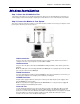
Chapter 1 – Introduction and Installation Modem Installation Step 1: Attach the Self-Adhesive Feet The modem comes with a set of self-adhesive plastic feet, which you can optionally attach to the modem. To install, simply peel them from their paper strip and press them into the recesses on the bottom of the modem. Step 2: Connect the Modem to Your System Turn off your computer.
Chapter 1 – Introduction and Installation Step 3: Install the Modem Driver If you use Windows 98+, you must install the modem driver, which is installed using the Windows Plug and Play feature. Follow the four-step procedure below. If you use another operating system, see the Appendix. 1. Make sure your modem is connected properly, and then turn on your computer. Windows should detect your new modem and open the Install New Modem wizard. 1. Insert the system CD, and then click OK. 2.
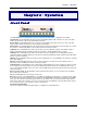
Chapter 2 – Operation Chapter 2 – Operation Front Panel The MT2834ZDX has ten LED indicators on the front panel that indicate status, configuration, and activity: Transmit Data. The TD LED lights when the modem is transmitting data to another modem. The state of the LED matches the TD circuit on pin 2 of the RS-232C/V.24 interface. Receive Data. The RD LED lights when the modem is receiving data from another modem. The state of the LED matches that of the RD circuit on pin 3 of the RS-232C/V.24 interface.
Chapter 3 – AT Commands, S-Registers, and Results Codes Chapter 3 – AT Commands, SRegisters and Result Codes AT Commands This section summarizes the AT commands for this modem. Command: Values: Description: AT Attention Code n/a The attention code precedes all command lines except A/, A:, and escape codes. Command: Values: Description: RETURN Key n/a Press the RETURN (ENTER) key to execute most commands. Command: Values: Description: A Force Answer Mode n/a Answer call before final ring.
Chapter 3 – AT Commands, S-Registers, and Results Codes Command: Values: Default: Description: $BAn Baud Adjust n = 0 or 1 0 $BA0 Set baud adjust off, speed conversion on. (Serial port speed is independent of modem data rate.) $BA1 Set baud adjust on, speed conversion off. (Serial port speed is same as modem data rate.) Command: Values: Default: Description: &Cn Carrier Detect Control n = 0, 1, 2, or 4 1 &C0 Force Carrier Detect high. &C1 Let Carrier Detect follow carrier signal.
Chapter 3 – AT Commands, S-Registers, and Results Codes Command: Values: Default: Description: %DPn Read Line Probe Data n = 0 or 1 0 %DP0 Do not read and store line probe information from DSP during handshake. %DP1 Read and store line probe information from DSP during handshake. Command: Values: Default: Description: >DTn DTMF Detection n = 0 or 1 0 >DT0 The modem will not detect DTMF tones. >DT1 The modem will detect and report DTMF tones when it is off-hook.
Chapter 3 – AT Commands, S-Registers, and Results Codes Command: Values: Default: Description: $En V.42 Error Correction at 300 bps n = 0 or 1 0 $E0 V.42 error correction at 300 bps disabled. $E1 V.42 error correction at 300 bps enabled. Command: Values: Default: Description: $EBn Asynchronous Word Length n = 0 or 1 0 $EB0 10-bit mode enabled. $EB1 11-bit mode enabled. Command: Values: Defaults: Description: %En Escape Sequence Options n = 0–5 1 and 4 %E0 Modem won’t escape. %E1 +++AT method.
Chapter 3 – AT Commands, S-Registers, and Results Codes Command: Values: Default: Description: $Hn Help Screens n = 1, 2, or 3 None $H1 Display Help Screen #1. $H2 Display Help Screen #2. $H3 Display Help Screen #3. Command: Values: Default: Description: In Inquire Product Codes n = 0, 1, or 2 None I0 Display modem ID number. I1 Display firmware version number. I2 Display modem description.
Chapter 3 – AT Commands, S-Registers, and Results Codes Command: Values: Default: Description: $MBn Modem Baud Rate n = speed 28800 (ZDX) or 33600 (ZDXb) $MB300 Originate call at 300 bps. $MB1200 Originate call at 1200 bps. $MB2400 Originate call at 2400 bps. $MB4800 Originate call at 4800 bps. $MB7200 Originate call at 7200 bps. $MB9600 Originate call at 9600 bps. $MB14400 Originate call at 14,400 bps. $MB16800 Originate call at 16, 800 bps. $MB19200 Originate call at 19,200 bps.
Chapter 3 – AT Commands, S-Registers, and Results Codes Command: Values: Default: Description: &Rn Clear to Send Control n = 0, 1, or 2 1 &R0 Let CTS state follow RTS state when on line. &R1 Force CTS high (on). &R2 Let CTS drop on disconnect for time set by S24, then go high again. Command: Values: Default: Description: &RAn Asymmetrical Bit Rate n = 0 or 1 0 &RA0 Enable asymmetrical bit rate in V.34 mode. &RA1 Disable asymmetrical bit rate in V.34 mode.
Chapter 3 – AT Commands, S-Registers, and Results Codes Command: Values: Default: Description: &SFn DSR/CD Interaction Control n = 0 or 1 0 &SF0 Select DSR to follow CD. &SF1 Select DSR to be independent. Command: Values: Default: Description: $SBn Serial Port Baud Rate n = speed 57600 $SB300 Set serial port to 300 bps. $SB1200 Set serial port to 1200 bps. $SB2400 Set serial port to 2400 bps. $SB4800 Set serial port to 4800 bps. $SB9600 Set serial port to 9600 bps. $SB19200 Set serial port to 19200 bps.
Chapter 3 – AT Commands, S-Registers, and Results Codes Command: Values: Default: Description: &Wn Store Configuration n = 0 or 1 1 &W0 Store current settings in NVRAM; load them at power-on or following the ATZ command instead of loading the factory defaults from ROM. W1 Clear user default settings from NVRAM. Command: Values: Default: Description: Xn Result Codes and Call Progress Selection n = 0–4 0 X0 Basic result codes ( CONNECT only); does not look for dial tone or busy signal.
Chapter 3 – AT Commands, S-Registers, and Results Codes Command: Values: Description: %%%AT Remote Configuration Escape Sequence n/a Initiates remote configuration mode while online with remote modem. The remote configuration escape character (%) is defined in register S13. Command: Values: Description: +++AT Escape Code n/a Puts modem in command mode (and optionally issues a command) while remaining on line. Enter +++AT, up to ten command characters (or as defined by S34), and a RETURN.
Chapter 3 – AT Commands, S-Registers, and Results Codes S-Registers Certain modem values, or parameters, are stored in memory locations called S-registers. Use the S command to read or to alter the contents of S-Registers (see previous section). Register Unit Range Default Description Register Unit Range Default Description Sets the number of rings until the modem answers. ATS0=0 disables autoanswer completely. 0 Counts the rings that have occurred. 43(+) Sets ASCII code for the escape code character.
Chapter 3 – AT Commands, S-Registers, and Results Codes Result Codes In command mode the MT2834ZDX can send responses, or result codes, to your computer. Result codes are used by communications programs and can also appear on your monitor. AT&Q0 selects Multi-Tech result codes with RELIABLE, LAPM, and COMPRESSED modifiers (default). AT&Q1 selects standard AT result codes without modifiers.
Chapter 4 – Troubleshooting Chapter 4 – Troubleshooting Your MultiModemZDX modem was thoroughly tested at the factory before it was shipped. If you are unable to make a successful connection, or if you experience data loss or garbled characters during your connection, it is possible that the modem is defective. However, it is more likely that the source of your problem lies elsewhere. The following symptoms are typical of problems you may encounter: • None of the LEDs light when the modem is on.
Chapter 4 – Troubleshooting • • • • • • • Your communication program settings might not match the physical port the modem is connected to. The serial cable might be plugged into the wrong connector—check your computer documentation to make sure. Or you might have selected a COM port in the program other than the one the modem is physically connected to—compare the settings in the program to the physical connection.
Chapter 4 – Troubleshooting • If the modem reports NO CARRIER, the phone was answered at the other end, but no connection was made. You might have dialed a wrong number, and a person answered instead of a computer, or you might have dialed the correct number but the other computer or software was turned off or faulty. Check the number and try again, or try calling another system to make sure your modem is working. Also, try calling the number on your telephone.
Chapter 4 – Troubleshooting There Are Garbage Characters on the Monitor • Your computer and the remote computer might be set to different word lengths, stop bits, or parities. If you have connected at 8-N-1, try changing to 7-E-1, or vice-versa, using your communication software. • 4 You might be experiencing line noise. Enable error correction, if it is disabled, or hang up and call again; you might get a better connection the next time.
Appendix A – Regulatory Compliance Appendix A – Regulatory Compliance Regulatory Compliance Regulatory Requirements for the United States FCC CFR47 Part 15 Regulation This equipment has been tested and found to comply with the limits for a Class B digital device, pursuant to 47 CFR Part 15 regulations. The stated limits in this regulation are designed to provide reasonable protection against harmful interference in a residential installation.
Appendix A – Regulatory Compliance FCC CFR47 Part 68 Telecom 1. This equipment complies with Part 68 of the 47 CFR rules and the requirements adopted by the ACTA. Located on this equipment is a label that contains, among other information, the registration number and ringer equivalence number (REN) for this equipment or a product identifier in the format: For current products is US:AAAEQ##Txxxx. For legacy products is AU7USA-xxxxx-xx-x. If requested, this number must be provided to the telephone company.
Appendix A – Regulatory Compliance Current Requirements for Label Content and Format Approved terminal equipment and approved protective circuitry shall prominently display the following information using the format shown below: • Responsible party • Product Identification • Equipment Code • Ringer Equivalence • Ringer Type • Indication that the product meets the requirements of 47 CFR Part 68 The information required by the first five items shall correspond to the records in the ACTA database of approved
Appendix A – Regulatory Compliance Regulatory Requirements for Canada The following requirements are established under section 69.3 of the Telecommunications Act for purposes of section 5 of the Telecommunications Apparatus Regulations.
Appendix A – Regulatory Compliance (e) Certification Numbers granted prior to the implementation of the above marking format are grandfathered. (i) For previously certified TE, the self-marking format shall consist of the old certification number preceded by “IC:” For example, if the certification number is “123 1234 A”, then the self-mark would read “IC: 123 1234 A”.
Appendix B – Technical Specifications Appendix B – Technical Specifications Your MT2834ZDX fax modem meets the following specifications: Model Numbers MT2834ZDX, MT2834ZDXb Data Rates (Modem) 33.6K and 31.2K (ZDXb only), 28.8, 26.4K, 24K, 19.2K, 16.8K, 14.4K, 12K, 9600, 7200, 4800, 2400, 1200 and 0-300 bps Data Rates (Fax) 14,400, 9600, 4800 and 2400 bps Data Format (Modem) Serial, Binary, Asynchronous Compatibility (Modem) ITU-T V.34, AT&T V.32terbo, ITU-T V.32bis, V.32, Bell 212A and 103/113, ITU-T V.
Appendix C – Warranty and Service Appendix C – Warranty and Service Multi-Tech Warranty Statement Multi-Tech Systems, Inc., (hereafter “MTS”) warrants that its products will be free from defects in material or workmanship for a period of two, five, or ten years (depending on model) from date of purchase, or if proof of purchase is not provided, two, five, or ten years (depending on model) from date of shipment.
Appendix C – Warranty and Service Repair Procedures for International Customers (Outside U.S.A. and Canada) Your original point of purchase Reseller may offer the quickest and most economical repair option for your Multi-Tech product. You may also contact any Multi-Tech sales office for information about the nearest distributor or other repair service for your Multi-Tech product. The Multi-Tech sales office directory is available at www.multitech.
Appendix D – WEEE Statement Appendix D - Waste Electrical and Electronic Equipment (WEEE) Statement July, 2005 The WEEE directive places an obligation on EU-based manufacturers, distributors, retailers and importers to take-back electronics products at the end of their useful life. A sister Directive, ROHS (Restriction of Hazardous Substances) complements the WEEE Directive by banning the presence of specific hazardous substances in the products at the design phase.
Index Index A AT commands.....................................................................8 AT Commands Answerback &A.............................................................8 Asymmetrical Bit Rate &RA .......................................14 Asynchronous Word Length $EB ................................11 AT Command Control %DC .........................................9 Auto Speed Detection in Answer Mode #A ...................8 Auto-Reliable Buffering $A ..........................................
Index L Label content and format ..................................................26 LED indicators....................................................................7 LINE Connection................................................................5 M modem driver installation ................................................6 Replacement Parts ............................................................ 31 Result codes .....................................................................