
- Multi-Tech User Guide Modem MTASR1-100

Chapter 1 - Introduction and Description
MTASR1-100
9
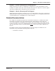
Back Panel
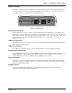
The cable connections for the RouteFinder are made at the back panel. Three groups of cables are
used on the RouteFinder, the Command Port, WAN link, and the Ethernet. The cable connections
are shown in Figure 1-3 and defined in the following groups.
10BASE T
OFF
RS232/V.35
POWER
COMMAND PORT
ON
10BASE 2
Figure 1-3. Back Panel
RS-232/V.35 Connector
The RS-232/V.35 connector is used to connect the RouteFinder to a WAN device. The WAN device
connection is to an asynchronous or synchronous communications device such as a modem, DSU, or
ISDN terminal adapter. This connection can be either RS232C or V.35. If the connection is V.35, then
the shunt must be moved from the default RS232 position to the V.35 position. This connector is a
DB25 male connector.
10Base T Connector
The 10Base-T connector is used to connect the RouteFinder to a LAN using unshielded twisted cable.
This connector is an RJ-45 jack.
10Base 2 Connector
The 10Base 2 connector is used to connect the RouteFinder to a LAN using thin coax cable.
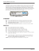
Command Port Connector
The Command Port connector is used to configure the RouteFinder using a PC with a serial port and
running Windows
®
software. The Command Port connector is an RJ-45 jack and a short adapter
cable is provided to convert to a standard serial port DB25 female connector.
Power Connector
The Power connector is used to connect the external power supply to the RouteFinder. The Power
connector is a 6-pin circular DIN connector. A separate power cord is connected to the power supply
and the live AC grounded outlet.
ON/OFF Switch
The power switch provides DC power to the RouterFinder when placed in the ON position and
removes power when placed in the OFF position.