
- Multi-Tech User Guide Modem MTASR1-100


Chapter 2 - Installation
MTASR1-100
15
Changing Shunt Position
The WAN port shunt must be moved to the V.35 position whenever you want to connect the
RouteFinder to an external composite link device with a V.35 interface. Do the following.
1. Ensure that the external power supply is disconnected from the RouteFinder.
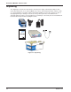
2. Turn the RouteFinder upside down and remove the cabinet mounting screw at the center back of
the cabinet.
Cabinet
Mounting
Screw
®
ETHERNET FAIL
POWER
RCV
XMT
COL
LNK
RCV
XMT
CTS
RTS
ERR
PWR
T
e
c
h
Systems
WAN LINK
CD
V35
Figure 2-2. Cabinet Mounting Screw
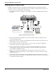
3. Turn the RouteFinder right side up, then slide the base out the rear of the cabinet.
5
6
7
8
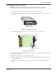
V.35 Shunt Position
RS232C Shunt Position (Default)
Back Panel Connectors
8-Position DIP Switch
RAM Sockets
LEDs
Figure 2-3. Shunt Positions
4. Pry the shunt out of the default RS-232 position, then insert the shunt in the V.35 position for the
WAN link (See Figure 2-3).
5. Slide the base all the way into the cabinet until it stops.
6. Turn the RouteFinder upside down and replace the cabinet mounting screw that was removed in
step 2 (See Figure 2-2).
7. Turn the RouteFinder right side up and connect the cables (Refer to the “Cabling your Router”
section).