MultiConnect Adapter Serial-to-Serial Adapter with IP User Guide
MultiConnect Adapter User Guide Serial-to-Serial Adapter (MTS2SA-T & MTS2SA-T-R) PN S000354A, Version A Copyright This publication may not be reproduced, in whole or in part, without prior expressed written permission from Multi-Tech Systems, Inc. All rights reserved. Copyright © 2004, by Multi-Tech Systems, Inc. Multi-Tech Systems, Inc.
Table of Contents Table of Contents Chapter 1 – Product Description & Specifications.................................................................................. 6 Product Description ................................................................................................................................... 6 Applications ............................................................................................................................................... 6 Types of Adapters Available..
Table of Contents Chapter 10 – Modem Mode AT Commands, S-Registers, Result Codes............................................. 85 Escape Code Sequence +++ .................................................................................................................. 85 Command Organization........................................................................................................................... 85 Command Types ...............................................................................
Table of Contents Chapter 14 – POP3 Client ....................................................................................................................... 153 Introduction............................................................................................................................................ 153 Setup and Configuration Prerequisites..................................................................................................
Chapter 1 – Product Description and Specifications Chapter 1 – Product Description & Specifications Product Description The MultiConnect serial-to-serial adapter enables installed serial devices to connect to the Internet for remote monitoring, control and configuration. Internet-Enable Any Device. The MultiConnect adapter provides the powerful ability to IP-enable serial devices allowing more options for data acquisition, device management, and industrial control than would otherwise be available.
Chapter 1 – Product Description and Specifications Types of Adapters Available Product Adapter Description Region MTS2SA-T Serial-to-Serial + IP (External Power) Global MTS2SA-T-R Serial-to-Serial + IP (RS-232 Power) Global Note: The RS-232–powered adapters are powered through the DSR pin of the RS-232 cable.
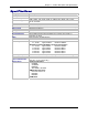
Chapter 1 – Product Description and Specifications Specifications Category Memory Flash Memory Protocols Supported Description 8 MEG 2 MEG ARP, DHCP, FTP, HTTP, ICMP, IP, POP3, PPP, SMTP, TCP, Telnet, TFTP, and UDP Standard DCE serial Serial Interface Serial, binary, asynchronous Data Formats 300; 1200; 2400; 4800; 9600; 19200; 38400; 57600; 115200; 230400 bps Data Rates RTS/CTS (hardware) Flow Control Serial; Telnet Management Username and password authentication using local database Security Flash ROM s
Chapter 1 – Product Description and Specifications Category Intelligent Features Software Features Description High performance 10/100BaseT Ethernet bridge Half duplex or full duplex support on the WAN interface 256 frame buffer Stores 10,000 MAC addresses Automatically learns MAC addresses Serial interface supports DTE speeds to 230K bps External and RS-232 power options High performance processor runs ARP, DHCP, FTP, HTTP, ICMP, IP, POP3, PPP, SMTP, SNMP, SNMP, TCP, Telnet, TFTP, UDP protocols Command l
Chapter 1 – Product Description and Specifications LED Indicators Name ACT STS Description Activity – Lit when data is being transmitted or received. Status – Blinks to indicate that the unit is functioning.
Chapter 2 – Installation Chapter 2 – Installation Attaching the MultiConnect to a Fixed Location The MultiConnect adapter is design to be used on the desktop or to be panel-mounted. To attach the bracket for panel-mounting, following these steps: 1. Typically, the MultiConnect adapter is mounted against a flat surface with two mounting screws. Drill the mounting holes at the desired location. The mounting holes must separated by 4 -7/16 inches center-to-center. 2.
Chapter 2 – Installation Serial-to-Serial Adapter Installation Connecting the Cables Serial-to-Serial Adapter Front Back shown with External Power Option 1. Plug one end of the RS-232 cable into the front of the Serial-to-Serial adapter. Plug the other end into the RS-232 connector on the modem that is setup with an Internet connection. 2. Plug one end of the other RS-232 cable into the back of the Serial-to-Serial adapter.
Chapter 2 – Installation Connecting the Power The adapters are powered in one of two ways: • Through the DSR Pin of the RS-232 Cable Adapters powered this way are shipped with an RS-232 cable that has a power pin instead of a DSR pin. • Through an External Power Supply Adapters powered this way are shipped with a universal power supply and its accompanying power cord and an RS-232 cable that has a DSR pin instead of a power pin. Connecting the External Power 1.
Chapter 3 – Managing and Configuring the MultiConnect Adapter Chapter 3 – Managing and Configuring the MultiConnect Adapter Two Ways to Login Login Using TTY • Use TTY to configure your MultiConnect IP for the first time. Configure the host serial port using the defaults listed below: Baud: 115.2K Data: 8 Parity: N Stop: 1 Flow-Control: None • Press the Enter key three times to get to the Login prompt or send three carriage returns. • At the Login prompt, type admin.
Chapter 4 – Command Line Interface (CLI) Chapter 4 – Command Line Interface (CLI) The MultiConnect commands are grouped based on the functionality. • General Setup Commands • IP Setup Commands • Serial Setup Commands • PPP Setup Commands • HTTP Setup Commands • SMTP Setup Commands • POP3 Setup Commands • FTP Client Setup Commands • SNTP Client Setup Commands General Notes • Required command parameters are indicated between < >. • Optional command parameters are indicated between [ ].
Chapter 4 – Command Line Interface (CLI) General Commands – Setup General Setup Commands General setup of a MultiConnect IP is port-independent (physical S0, S1 etc.). The following command set is used to set the global configuration of MultiConnect IP.
Chapter 4 – Command Line Interface (CLI) General Commands – Setup Command Syntax Description Default Value Success Error reset modem At will, reset the built-in modem. NA OK 1. Too few arguments Possible argument(s) are modem Command Syntax Description Default Value Success save Command to Save the configuration to the flash and reboot. NA OK Command Syntax Description telnet [] Manual serial dial-in (device port to modem port connectivity). Invoked from the command shell. NA OK 1.
Chapter 4 – Command Line Interface (CLI) General Commands – Setup Command Syntax Description Default Value Success Error Command Syntax Description Default Value Success Error Command Syntax Description Default Value Success Error Command Syntax Description Default Value Success Error user password Change the password for a user. NA OK 1. Too few arguments “Too few arguments. Possible value(s) are username followed by password” 2.
Chapter 4 – Command Line Interface (CLI) General Commands – Setup Command Syntax Description Default Value Success Error set login Prompts the Login for the command shell when enabled, and doesn't when disabled. Enable OK 1. Too few arguments "Usage: set login Type 'set login ?' for more information" 2.
Chapter 4 – Command Line Interface (CLI) General Commands – Setup Command Syntax Description Default Value Success Error show buildrun Command Line Configuration - History. Upon invoking any command, either through Telnet or Serial TTY, the command is added to the buildrun file. This is very useful in case of version updates. NA OK 1. Too few arguments "Too few arguments. Possible argument(s) are serial date statistics users buildrun ip sys-info configuration ppp time 2.
Chapter 4 – Command Line Interface (CLI) General Commands – Show Command Syntax Description Default Value Success Error show statistics Displays MultiConnect IP statistics. NA OK 1. Too few arguments “Too few arguments. Possible argument(s) are: ip statistics users configuration ppp sys-info date serial time 2. Invalid argument Valid arguments are: ip statistics users configuration ppp sys-info date serial time Command Syntax Description show sys-info Displays the system related information.
Chapter 4 – Command Line Interface (CLI) General Commands – Show Command Syntax Description Default Value Success Error show users Displays the configured users. NA OK 1. Too few arguments “Too few arguments. Possible argument(s) are: serial ip sys-info configuration ppp time date statistics users 2. Invalid argument Valid arguments are: serial ip sys-info configuration ppp time date statistics users Multi-Tech Systems, Inc.
Chapter 4 – Command Line Interface (CLI) IP Commands – Setup IP Setup Commands Command Syntax Description Default Value Success Error set ip dns Enables/disables the DNS client. Enabled OK 1. Too few arguments “Usage: set ip dns Type ‘set ip dns ?’ for more information” 2. Invalid string Type ‘set ip dns ?’ for more information” Command Syntax Description Default Value Success Error set ip hostname Sets the host name of the MultiConnect IP.
Chapter 4 – Command Line Interface (CLI) IP Commands – Setup Command Syntax Description Default Value Success Error set ip syslogd-server Sets the remote syslog server's IP address. 0.0.0.0 OK 1. Too few arguments “Usage: set ip syslogd-server Type ‘set ip syslogd-server ?’ for more information” 2.
Chapter 4 – Command Line Interface (CLI) IP Commands – Setup Command Syntax Description Default Value Success Error Command Syntax Description Default Value Success Error set ip telnet auto-dialout Enables Telnet connectivity between the MultiConnect IP and the remote device. This flag enables/disables the Telnet Auto dialout globally. Enabled OK 1. Too few arguments “Usage: set ip telnet auto-dialout Type ‘set ip telnet auto-dialout ?’ for more information” 2.
Chapter 4 – Command Line Interface (CLI) IP Commands – Setup Command Syntax Description Default Value Success Error Command Syntax Description Default Value Success Error Command Syntax Description Default Value Success Error Command Syntax Description Default Value Success Error set ip telnet inactivity-timeout If the Telnet session is inactive for ‘t’ secs, the connection is terminated. This functionality is applicable only if “set telnet inactivity” is enabled.
Chapter 4 – Command Line Interface (CLI) Serial Commands – Setup Serial Setup Commands Command Syntax Description Default Value Success Error Command Syntax Description Default Value Success Error Command Syntax Description Default Value Success Error set serial auto-telnet This command globally enables serial auto dial-in support.
Chapter 4 – Command Line Interface (CLI) Serial Commands – Setup Command Syntax Description Default Value Success Error Command Syntax Description Default Value Success hangup [serial interface] Valid serial interface – Modem port S1 When this command is issued, the established live link is brought down. This command is only valid only for modem port (S1) If physical link is brought down, OK and Physical link is successfully brought down messages are given 1.
Chapter 4 – Command Line Interface (CLI) Serial Commands – Setup Command Syntax Description Default Value Success Error Command Syntax Description Default Value Success Error set serial [s0] auto-dialin Enables/disables the device port to Internet connectivity for the serial port S0. This command is valid only for device port S0 Disabled OK 1. Too few arguments “Usage: set serial s0 auto-dialin Type ‘set serial s0 auto-dialin ? for more information” 2.
Chapter 4 – Command Line Interface (CLI) Serial Commands – Setup Command Syntax Description Default Value Success Error Command Syntax Description Default Value Success Error set serial [s0] auto-dialin-port [port_num] Command to specify the auto dial-in port number. Note: [port_num] is optional here. If port_num is not specified, the standard port 23 of the Telnet protocol shall be used. This command is valid only for device port S0 23 OK 1.
Chapter 4 – Command Line Interface (CLI) Serial Commands – Setup Command Syntax Description Default Value Success Error set serial [s0] auto-dialin trig-mode This mode is applicable only when auto dial-in is enabled on the serial port S0. This command is valid only for device port S0. Parameter Description char Initiate a session (Telnet) to the auto-dialin-ipaddress, only on a reception of a character on the serial port S0.
Chapter 4 – Command Line Interface (CLI) Serial Commands – Setup Command Syntax Description Default Value Success Error Command Syntax Description Default Value Success Error Command Syntax Description Default Value Success Error set serial [s0] auto-dialout-port If auto-dialout is enabled, specifies the auto dialout-port on which the client can connect. Default is 5000. Note: The port number should be other than standard TCP ports. This command is valid only for device port S0. 5000 OK 1.
Chapter 4 – Command Line Interface (CLI) Serial Commands – Setup Command Syntax Description Default Value Success Error Command Syntax Description set serial [s0/s1] buffer-datasize <0/d bytes> This command primarily buffers the data. 0 – No buffering. OK 1. Too few arguments “Usage: set serial s0/s1 buffer-datasize <0/d bytes> Type ‘set serial s0/s1 buffer-datasize ?’ for more information” 2. Multiple matches buffer-datasize buffer-time 3.
Chapter 4 – Command Line Interface (CLI) Serial Commands – Setup Command Syntax Description Default Value Success Error Command Syntax Description Default Value Success Error set serial [s0/s1] chat-script Sets expect and send strings for the chat script to act on the modem. Triggers for a reboot upon save. Important Note: Use double quotes if more than one word is used in the /. NA OK 1.
Chapter 4 – Command Line Interface (CLI) Serial Commands – Setup Command Syntax Description Default Value Success Error Command Syntax Description Default Value Success Error Command Syntax Description Default Value Success Error Command Syntax Description Default Value Success Error Set serial [s0/s1] flow-control Set the flow-control of the serial port. By default flow-control is disabled on the serial port. rts-cts OK 1.
Chapter 4 – Command Line Interface (CLI) Serial Commands – Setup Command Syntax Description Default Value Success Error Command Syntax Description Default Value Success Error Command Syntax Description Default Value Success Error set serial [s0/s1] modem dial-prefix Sets the Modem Dial-Prefix. Triggers for a reboot upon save. Note: The configured modem strings takes precedence over the MODEM.CNF ATDT OK 1.
Chapter 4 – Command Line Interface (CLI) Serial Commands – Setup Command Syntax Description Default Value Success Error Command Syntax Description Default Value Success Error Command Syntax Description Default Value Success Error set serial [s1] modem dialing-trig-mode Sets the dialing trigger mode for the modem port S1. If dialing trig mode is none: The serial interface will initialize the modem and dial as per the configured parameters.
Chapter 4 – Command Line Interface (CLI) Serial Commands – Setup Command Syntax Description Default Value Success Error Command Syntax Description Default Value Success Error Command Syntax Description Default Value Success Error Command Syntax Description Default Value Success Error set serial [s0/s1] modem init-string Configures the modem initial strings. Init-num can range from 1-5. Triggers for a reboot upon save.
Chapter 4 – Command Line Interface (CLI) Serial Commands – Setup Command Syntax Description Default Value Success Error Command Syntax Description Default Value Success Error Command Syntax Description Default Value Success Error set serial [s0] login-string Sets a login-string to the serial port. This command is valid only for port S0. The Login string can be of length maximum 8 characters.
Chapter 4 – Command Line Interface (CLI) Serial Commands – Setup Command Syntax Description Default Value Success Error set serial [s0/s1] stop-bits <1/1.5/2> Sets the stop bits. 1 OK 1. Too few arguments “Usage: set serial s0/s1 stop-bits <1/1.5/2> Type ‘set serial s0/s1 stop-bits ?’ for more information” 2. Invalid stop-bit setting “ERROR: Stop-bit supported : [1, 1.
Chapter 4 – Command Line Interface (CLI) Serial Commands – Show Command Syntax Description Default Value Success Error Command Syntax Description Default Value Success Error show serial [s0/s1] statistics Displays Serial Statistics. • Status (If serial is used by any application) • Rx Bytes • Rx Errors • Tx Bytes • Tx Errors • Status of EIA signals (CTS, DSR, DCD, RTS, DTR). Important Note: Serial statistics are only for the current session.
Chapter 4 – Command Line Interface (CLI) PPP Commands – Setup PPP Setup Commands Note: All PPP Commands use the ppp0 interface, which corresponds to the modem port S1. Command Syntax Description Default Value Success Error set ppp authentication Enables/disables PPP Authentication. Disabled OK 1. Too few arguments Possible argument(s) are disable and enable 2. Invalid string Invalid argument. Valid argument(s) are disable and enable 3.
Chapter 4 – Command Line Interface (CLI) PPP Commands – Setup Command Syntax Description Default Value Success Error Command Syntax Description Default Value Success Error Command Syntax Description Default Value Success Error Command Syntax Description Default Value Success Error set ppp dialing-max-retries <0-100> Configures the maximum number of dialing retries. Maximum dialing retry is 100 5 OK 1.
Chapter 4 – Command Line Interface (CLI) PPP Commands – Setup Command Syntax Description Default Value Success Error set ppp local-ip-addr mask During IPCP negotiations, the configured IP address is sent for the local interface. In the case where the peer is requested to provide the IP address, it can be configured as 0.0.0.0 0.0.0.0 255.255.255.0 OK 1. Too few arguments Possible arguments are IP Address and Mask 2.
Chapter 4 – Command Line Interface (CLI) PPP Commands – Show Command Syntax Description Default Value Success Error Command Syntax Description Default Value Success Error Command Syntax Description Default Value Success Error show ppp ppp0 configuration Displays: PPP Status (enabled/disabled) Authentication status Authentication type Username and password for authentication Compression status Compression type IPCP Mode Local IP Address Remote IP Address NA OK 1.
Chapter 4 – Command Line Interface (CLI) PPP Commands – Show Command Syntax Description Default Value Success Error show ppp statistics Displays PPP Statistics. OK 1. Too few arguments Possible argument(s) are configuration ip-addr statistics link-status 2. Invalid argument Invalid argument Valid argument(s) are: configuration ip-addr statistics link-status Multi-Tech Systems, Inc.
Chapter 4 – Command Line Interface (CLI) HTTP Server Commands – Setup HTTP Server Commands The commands in this section are listed in the order in which they might be used. Command Syntax Description Default Value Success Error set ip http-page This parameter is used by the http server to host the default HTML index or host-defined http-serial-S0 HTML page. Default OK 1. Too few arguments “Usage: set ip http-page Type set ip http-page ?” 2.
Chapter 4 – Command Line Interface (CLI) HTTP Server Commands – Setup Command Syntax Description Default Value Success Error save param Invoking this command will save the host parameters into the flash. The “/var/apps” directory is gun zipped to apps.tar.gz and written into flash. (APPS _SECTOR) OK 1.
Chapter 4 – Command Line Interface (CLI) SMTP Client Commands – Setup SMTP Client Commands The commands in this section are listed in the order in which they might be used. Command Syntax Description Default Value Success Error set send-mail smtp-server-name Sets the SMTP server name or IP address. Server names must be such that they can be resolved by the DNS. NULL OK 1.
Chapter 4 – Command Line Interface (CLI) SMTP Client Commands – Setup Command Syntax Description Default Value Success Error Command Syntax Description Default Value set send-mail to-address where n = 1 to 5. Sets the email-address as one of the primary addressee. This is the default email address to which email messages are sent. NULL OK 1. Too few arguments “Usage: set send-mail to-address Type 'set send-mail to-address ?' for more information” 2.
Chapter 4 – Command Line Interface (CLI) SMTP Client Commands – Setup Command Syntax Description Default Value Success Error Command Syntax Description Default Value Success Error send-mail [-b] [-t ] [-c ] [-s ] [-d ] Triggers the SMTP Client application. The application enters the interactive mode or sends the mail according to the command arguments. Notes: All the arguments are optional.
Chapter 4 – Command Line Interface (CLI) POP3 Client Commands – Setup POP3 Client Commands Command Syntax Description Default Value Success Error Command Syntax Description Default Value Success Error set recv-mail server-name This parameter is set by the host to establish the POP3 connection for receiving the email from the remote server. This also needs DNS to be enabled on the MultiConnect IP. None OK 1.
Chapter 4 – Command Line Interface (CLI) POP3 Client Commands – Setup Command Syntax Description Default Value Success Error Command Syntax Description Default Value Success Error Command Syntax Description Default Value Success Error Command Syntax Description Default Value Success Error Command Syntax Description Default Value Success Error set recv-mail leave-on-server Set the variable “leave a copy of message on server” flag, which tells the POP3 server not to delete the emails
Chapter 4 – Command Line Interface (CLI) POP3 Client Commands – Setup Command Syntax Description Default Value Success Error recv-mail top Displays the first lines of the mail corresponding to index. If n is greater the email size then the whole message is displayed. OK 1.
Chapter 4 – Command Line Interface (CLI) FTP Client Commands – Setup FTP Client Commands Command Syntax Description Default Value Success Error Command Syntax Description Default Value Success Error set ftp device login [password [account ] Sets/clears the device login name, password and account password details that will be used by FTP for automatic authentication.
Chapter 4 – Command Line Interface (CLI) FTP Client Commands – Setup Command Syntax Description Default Value Success Error ftp < [-l] [-t] [-r] > [-p] Triggers the FTP client to establish the FTP session with the remote server and to perform the required action according to the specified option. -p : Opens the Data connection in Passive mode. (If this option is not given, the data connection will be opened in Active mode by default).
Chapter 4 – Command Line Interface (CLI) SNTP Client Commands – Setup SNTP Client Commands Command Syntax Description Default Value Success Error Command Syntax Description Default Value Success Error set sntp client Starts the SNTP Client to contact the configured server on UDP port 123 and set the local time. Disable OK 1.
Chapter 4 – Command Line Interface (CLI) SNTP Client Commands – Setup Command Syntax Description Default Value Success Error set sntp-client polling-time where value = 2 to 1440 Sets the polling time at which SNTP client requests the server to update the time. 300 OK 1. Invalid arguments "error: Invalid Polling time" 2.
Chapter 4 – Command Line Interface (CLI) SNTP Client Commands – Setup Command Syntax Description Default Value Success Error Command Syntax Description Default Value Success Error Command Syntax Description Default Value Success Error Command Syntax Description Default Value Success Error set sntp-client daylight-saving start-weekday where dayofweek = sunday, monday ... Saturday Sets the start weekday to use during the Day Light Saving Mode. Sunday OK 1.
Chapter 4 – Command Line Interface (CLI) SNTP Client Commands – Setup Command Syntax Description Default Value Success Error Command Syntax Description Default Value Success Error Command Syntax Description Default Value Success Error set sntp-client daylight-saving end-weekday where dayofweek = Sunday, Monday … Saturday Sets the end weekday to use during the Day Light Saving Mode. Sunday OK 2. Invalid arguments „error: Invalid end day of the week“ 2.
Chapter 5 – Setting Country or Region Codes Using the CLI Chapter 5 – Setting Country or Region Codes Using the CLI The Default Country or Region Code is B5. If You Want to Change the Country or Region Code, Use the Command Line Interface: Command Syntax Description Default Value Success Error set serial s1 modem country-code value Sets the modem country code value to . This command is valid only for port S1. Applicable only if the country-code type is set to code. OK 1.
Chapter 6 – Prerequisite Configurations Chapter 6 – Prerequisite Configurations This chapter covers prerequisite tasks, those tasks or configurations that must be completed before you can set up certain operating scenarios. Other prerequisite tasks related to specific operating scenarios are described throughout the rest of this document. 1. MultiConnect IP Communication Interfaces and Conventions The Serial Interface ports, S0 and S1, correspond to Device Port and Modem Port respectively.
Chapter 6 – Prerequisite Configurations 2. MultiConnect IP Modes of Operation The MultiConnect IP can function in two modes: • Transparent Mode When the MultiConnect IP is configured to function in the modem operation mode, it functions as a modem. The Host/Serial device connected on the device port can use the MultiConnect IP as a modem in transparent mode. Refer to Chapter 9 for application examples that use Transparent Mode.
Chapter 6 – Prerequisite Configurations 3. Physical Link Established over the Modem Port For any application such as SMTP Client, HTTP Server, POP3 Client, etc. to function, the PPP link must be opened up on the modem port.
Chapter 7 – Telnet Dialout Chapter 7 – Telnet Dialout Introduction Telnet Dialout Feature The Telnet feature allows you to access the serial port and establish two-way traffic between the Telnet/RAW-TCP client and the serial device. This chapter provides examples of a Telnet client on an IP network (over the modem port) connecting to a remote serial device. The MultiConnect IP acts as a Terminal Server using the Telnet dialout feature.
Chapter 7 – Telnet Dialout Optional Configuration Commands (Return to Scenario 1 - Setup Manual Dialout Notes:) (Return to Scenario 2 - Auto Dialout Prerequisites) (Return to Scenario 3 - Auto Dial-out in RAW-Mode Notes:) The following commands can be used for optional configurations: • Enable/Disable the Authentication for Dial-out session # set login auto-dialout-login • Enable/Disable the Switching-between-Dialout & Command Prompt feature # set ip telnet escape-monitor
Chapter 7 – Telnet Dialout Scenario 1 – Manual Dialout Connect to the MultiConnect IP using a Telnet Client on port 23 (configuration port). At the command prompt, invoke # dialout serial s0. Once the session is opened successfully, there can be two-way traffic between the Telnet client and the serial device. • You can switch from Command Prompt to Dialout session using the restore session command. • You can switch from Dialout session to Command Prompt using .
Chapter 7 – Telnet Dialout MultiConnect IP Manual Dialout Setup Commands # # # # # set set set set set serial serial serial serial serial s0 s0 s0 s0 s0 stop-bits 1 baud-rate 115200 data-bits 8 parity none flow-control rts-cts # # # # # # # set set set set set set set serial serial serial serial serial serial serial s1 s1 s1 s1 s1 s1 s1 stop-bits 1 baud-rate 115200 data-bits 8 parity none flow-control rts-cts connect-type modem modem dial-number 123 # set serial s1 modem dialing-trig-mode none (R
Chapter 7 – Telnet Dialout Scenario 2 – Auto Dialout In this scenario, the Auto Dialout session in Telnet mode is opened using a Telnet client. Prerequisites RAW mode (global and each port) MUST BE DISABLED using the Optional Configuration Commands. A Telnet client can open an auto Dialout session by specifying the configured auto-dialout port. • Once the session is opened successfully, there can be two-way traffic between the Telnet session and the remote serial device.
Chapter 7 – Telnet Dialout MultiConnect IP Auto Dialout in Telnet Mode Setup Commands # set ip telnet auto-dialout enable # set serial s0 auto-dialout enable # set serial s0 auto-dialout-port 5000 # set serial s0 auto-dialout-protocol telnet # # # # # set set set set set serial serial serial serial serial s0 s0 s0 s0 s0 baud-rate 115200 data-bits 8 parity none stop-bits 1 flow-control rts-cts # # # # # # # set set set set set set set serial serial serial serial serial serial serial s1 s1 s1 s1 s1 s
Chapter 7 – Telnet Dialout Scenario 3 – Auto Dialout in RAW Mode In this scenario, the Auto-Dialout session in RAW mode is opened using a RAW-TCP client. Prerequisites RAW mode (Global and each port) MUST BE ENABLED using the Optional Configuration Commands. The Auto Dialout session can be opened by a RAW-TCP client by specifying the auto-dialout configured port. Once the session is opened successfully, there can be two-way traffic between the Telnet session and the remote serial device.
Chapter 7 – Telnet Dialout Commands to Setup Auto Dial-out in RAW-Mode for MultiConnect IP # set ip telnet auto-dialout enable # set ip telnet raw-mode enable # # # # # set set set set set serial serial serial serial serial s0 s0 s0 s0 s0 stop-bits 1 baud-rate 115200 data-bits 8 parity none flow-control rts-cts # # # # set set set set serial serial serial serial s0 s0 s0 s0 auto-dialout enable raw-dialout enable auto-dialout-port 5000 auto-dialout-protocol telnet # # # # # # # set set set set se
Chapter 8 – Auto Dial-in Feature Chapter 8 – Auto Dial-in Feature Introduction The auto dial-in feature enables the MultiConnect IP to act as a Telnet client thus facilitating the serial device to access any Telnet/terminal servers on the IP network (over the built-in modem interface). Once the session (Serial Client to Server) is opened successfully, it allows two-way traffic between the serial device and the remote server.
Chapter 8 – Auto Dial-in Feature Scenario 1 – Manual Serial Dial-in Login to the Command prchat-scriptompt from the serial side. Invoke # telnet at the command prompt. Once the session is opened successfully, there can be two-way traffic between the serial device and the remote server. • You can switch from Command Prompt to Dial-in session using the restore session command. • You can switch from Dial-in session to Command Prompt using .
Chapter 8 – Auto Dial-in Feature MultiConnect IP Manual Dial-In Setup Commands # # # # # set set set set set serial serial serial serial serial s0 s0 s0 s0 s0 baud-rate 115200 data-bits 8 parity none stop-bits 1 flow-control rts-cts # # # # # # # set set set set set set set serial serial serial serial serial serial serial s1 s1 s1 s1 s1 s1 s1 baud-rate 115200 data-bits 8 parity none stop-bits 1 flow-control rts-cts connect-type modem modem dial-number 123 # set serial s1 modem dialing-trig-mode n
Chapter 8 – Auto Dial-in Feature Scenario 2 – Serial Auto Dial-in in Telnet Mode This example shows how to setup a serial auto dial-in session in Telnet mode. The auto dial-in session is opened by Telnet client embedded in the MultiConnect IP to the configured server on a configured port. Once the session is opened successfully, there can be two-way traffic between the serial device and the remote server. • You can switch from Command Prompt to Dial-in session using the restore session command.
Chapter 8 – Auto Dial-in Feature MultiConnect IP Auto Dial-In Setup in Telnet Mode Commands # # # # # # set set set set set set serial serial serial serial serial serial auto-telnet enable s0 auto-dialin enable s0 auto-dialin trig-mode dtr-char s0 auto-dialin-ipaddress 202.54.39.
Chapter 8 – Auto Dial-in Feature Scenario 3 – Auto Dial-in Session in RAW Mode This scenario shows how to configure an auto dial-in session in RAW mode. The auto dial-in session is opened by Telnet client (embedded in the MultiConnect IP) in RAW-mode to the configured server on a configured port number. Once the PPP link is up with an IP address, the auto dial-in session can be probed as in the Auto Dial-In scenario below.
Chapter 8 – Auto Dial-in Feature Scenario 4 – Serial Tunneling Mode The scenario shows a serial tunnel established between two serial devices (Serial Device-1, Serial Device-2) using two MultiConnect IP modules, which are located apart geographically. Once the PPP link is up with an IP address on S1, the dial-in session can occur. The Serial Devices then communicate to each other across the MultiConnect IP modules. Serial Tunneling Multi-Tech Systems, Inc.
Chapter 8 – Auto Dial-in Feature Commands for Serial Tunneling Setup Using Two MultiConnect IP Modules Commands for MultiConnect IP Module 1 (Configure for Serial Auto Dial-in) # set ip telnet raw-mode enable # set serial auto-telnet enable # set serial s0 auto-dialin enable # set serial s0 raw-dialin enable # set serial s0 auto-dialin trig-mode dtr-char # set serial s0 auto-dialin-ipaddress 202.54.39.
Chapter 9 – Modem (Transparent) Mode Chapter 9 – Modem (Transparent) Mode Introduction In the modem mode (also called transparent mode), raw data is communicated between serial ports 1 and 2.
Chapter 9 – Modem (Transparent) Mode Scenario 1 – MultiConnect IP as a Modem In this scenario, once the physical link is up on the built-in modem interface; i.e., by dialing or answering, Multi-Tech Systems, Inc.
Chapter 9 – Modem (Transparent) Mode Scenario 2 – Serial Tunneling in Transparent Mode In this scenario, two MultiConnect IP modules in transparent mode aid in the communication between two serial devices that are connected to the RS-232 interface (S0) of the MultiConnect IP modules. Serial tunneling is achieved in the transparent mode where raw data is communicated. Serial Tunneling in Transparent Mode Multi-Tech Systems, Inc.
Chapter 9 – Modem (Transparent) Mode Commands for MultiConnect IP - 1 (Dialing End) # set operation-mode modem # set serial s0 escape-monitor enable # set serial s0 escape-string "+++inets0" # # # # # set set set set set serial serial serial serial serial s0 s0 s0 s0 s0 stop-bits 1 baud-rate 115200 data-bits 8 parity none flow-control rts-cts # # # # # # set serial set serial set serial set serial set serial save s1 s1 s1 s1 s1 stop-bits 1 baud-rate 115200 data-bits 8 parity none flow-control rts-c
Chapter 10 − Modem Mode AT Commands, S-Registers, and Result Codes Chapter 10 – Modem Mode AT Commands, S-Registers, Result Codes This chapter covers the V.22bis, V.32, V.34, and V.92 commands, S-Registers, and Result Codes. The AT commands are used to control the operation of your modem. They are called AT commands because the characters AT must precede each command to get the ATtention of the modem. AT commands can be issued only when the modem is in command mode or online command mode.
Chapter 10 − Modem Mode AT Commands, S-Registers, and Result Codes Command Types The following list should help if you are looking for a particular type of command. This list categorizes AT Commands by function.
Chapter 10 − Modem Mode AT Commands, S-Registers, and Result Codes Call Control Commands +MS +MR %E %U B Modulation Selection Modulation Reporting Control Enable/Disable Line Quality Monitor and Auto-Retrain Select µ-Law or A-Law Codec Type Communication Standard – CCITT or Bell Error Control Commands +ES +EB +ESR +EFCS +ER +ER +ETBM \B \K -K Error Control Break Handling in Error Control Operation Selective Repeat 32-bit Frame Check Sequence Error Control Reporting Report the Current Error Contro
Chapter 10 − Modem Mode AT Commands, S-Registers, and Result Codes Command Detail Command: Values: Description: AT Command: Values: Description: Command: Values: Attention Code n/a The attention code precedes all command lines except for escape sequences. ENTER Key n/a Press the ENTER (RETURN) key to execute most commands. A Description: Answer n/a Answer call before final ring. The modem will go off-hook and attempt to answer an incoming call if correct conditions are met.
Chapter 10 − Modem Mode AT Commands, S-Registers, and Result Codes Select pulse dialing: pulse dial the numbers that follow until a "T" is encountered. Affects current and subsequent dialing. Some countries prevent changing dialing modes after the first digit is dialed. T Select tone dialing: tone dial the numbers that follow until a "P" is encountered. Affects current and subsequent dialing. Some countries prevent changing dialing modes after the first digit is dialed.
Chapter 10 − Modem Mode AT Commands, S-Registers, and Result Codes Command: In Identification (for V.22bis) This command causes the modem to reports the requested result according to the command parameter. Values: Default: n = 0–7 None I0 I1 Reports product code, e.g., “2400”. Reports the least significant byte of the stored checksum in decimal. Reports 255 if the prestored checksum value is FFh. I2 Check ROM and verify the checksum, displaying OK or ERROR.
Chapter 10 − Modem Mode AT Commands, S-Registers, and Result Codes Command: Values: Default: Description: P Set Pulse Dial Default P, T T This command forces pulse dialing until the next T dial modifier of T command is received. As soon as a dial command is executed which specifies the dialing mode for that particular call (e.g., ATDT…), this command is overridden so that all future dialing will be tone dialed. (See T command). This command may not be permitted in some countries.
Chapter 10 − Modem Mode AT Commands, S-Registers, and Result Codes Command: Values: Default: Description: Xn Extended Result Codes and Call Progress Information n = 0–4 4 This command selects the subset of the result code messages used by the modem to inform the DTE of the results of commands. See Extended Results Code Chart in the Results Code section of this chapter.
Chapter 10 − Modem Mode AT Commands, S-Registers, and Result Codes Command: Values: Default: Description: &Fn Restore Factory Configuration (Profile) n=0 None The modem loads the factory default configuration (profile). The factory defaults are identified for each command and in the S-Register descriptions. A configuration (profile) consists of a subset of S-Registers. &F0 Restore factory configuration 0. &F1 Restore factory configuration 1. (Not available in V.22bis).
Chapter 10 − Modem Mode AT Commands, S-Registers, and Result Codes Command: Values: Default: Description: Command: Values: Description: &Tn &V Local Analog Loopback Test n = 0, 1, None The modem can perform the local analog loopback test if &T1 is selected. The test can be run only when the modem is operating in asynchronous mode with non-error-correction (normal). To terminate a test in progress, the escape sequence (+++) must be entered first. &T0 Stops any test in progress. Clears S16.
Chapter 10 − Modem Mode AT Commands, S-Registers, and Result Codes Command: Values: Default: Description: &V1 Display Last Connection Statistics (&V1 has no functionality in V.22bis) n=1 1 Displays the last connections in the following format (shown with typical results): TERMINATION REASON.......... LOCAL REQUEST LAST TX rate................ 26400 BPS HIGHEST TX rate............. 26400 BPS LAST RX rate................ 49333 BPS HIGHEST RX rate………… 49333 BPS PROTOCOL…………..
Chapter 10 − Modem Mode AT Commands, S-Registers, and Result Codes Command: Values: Default: Description: &Zy=x Store Telephone Number (Not available in V.22bis) y = 0–3 x = Dialing command None Stores up to four telephone numbers and each telephone number dial string can contain up to 31 digits (requires 256-byte NVRAM installed).
Chapter 10 − Modem Mode AT Commands, S-Registers, and Result Codes Command: Values: Default: \Nn Description: Command: Values: Default: Description: Operating Mode – Error Correction n = 0–5 5 Controls the preferred error-correcting mode to be negotiated in a subsequent data connection. \N0 Selects normal speed buffered mode (disables error-correction mode). \N1 Serial interface selected - Selects direct mode and is equivalent to &M0 mode of operation. \N2 Selects reliable (error-correction) mode.
Chapter 10 − Modem Mode AT Commands, S-Registers, and Result Codes Command: Values: Default: Description: –Kn Command: Values: Default: Description: –STEn Set Telephony Extension n = 0 or 1 1 The –STE command enables/disables Line-In-Use, Extension Pickup, and Remote Hangup detection features. Note: This command is supported only if enabled through firmware configuration. Defined Values: Decimal number corresponding to the selected bit-mapped options.
Chapter 10 − Modem Mode AT Commands, S-Registers, and Result Codes Case 3: Telephone Line is Not Connected to Modem If an ATDT, ATDP or ATDL is issued while Line-In-Use detection is enabled and the telephone line is not connected, the modem will go off-hook momentarily, go back onhook, then respond with NO DIAL TONE message.
Chapter 10 − Modem Mode AT Commands, S-Registers, and Result Codes Command: %Ln Line Signal Level Report Returns a value, which indicates the received signal level. The value returned is a direct indication (DAA dependent) of the receive level at the MDP, not at the telephone line connector. For example, 009 = -9 dBm, 043 = -43 dBm, and so on. Command: %Qn Line Signal Quality Report Reports the line signal quality (DAA dependent). Returns the higher order byte of the EQM value.
Chapter 10 − Modem Mode AT Commands, S-Registers, and Result Codes Command: +A8I CI Signal Indication (Not available in V.22bis) This indication is issued by an answering modem, if +A8E, does not equal 0, to indicate detection of a V.8 CI signal, and report the recovered Call Function octet(s). Indication Syntax: +A8I: Example +A8I:0 The modem timed out waiting for CI. +A8I:X YYY Command: Values: Default: Description: +DR Data Compression Report (Not available in V.
Chapter 10 − Modem Mode AT Commands, S-Registers, and Result Codes Command: Values: Description: +EB Command: Values: Description: +EFCS 32-bit Frame Check Sequence (Not available in V.22bis) n/a This extended-format numeric parameter controls the use of the 16-bit or 32-bit frame check sequence (FCS) option in V.42.
Chapter 10 − Modem Mode AT Commands, S-Registers, and Result Codes Command: Description: +ES Defined Values: Command: Values: Description: +ESR Error Control Selection This extended-format command specifies the initial requested mode of operation when the modem is operating as the originator, optionally specifies the acceptable fallback mode of operation when the modem is operating as the originator, and optionally specifies the acceptable fallback mode of operation when the modem is operating as the a
Chapter 10 − Modem Mode AT Commands, S-Registers, and Result Codes Command: Values: Description: +ETBM Call Termination Buffer Management n/a This extended-format compound parameter controls the handling of data remaining in modem buffers upon call termination.
Chapter 10 − Modem Mode AT Commands, S-Registers, and Result Codes Command: Values: +IFC DTE-Modem Local Flow Control 0, 1 Values defined by Specifies the method to be used by the DTE to control the flow of received data from the modem. +IFC0 None +IFC1 XON/XOFF on transmitted data (XON/XOFF on transmit data); do not pass XON/XOFF characters to the remote modem. +IFC2 Circuit 133 (Ready for Receiving).
Chapter 10 − Modem Mode AT Commands, S-Registers, and Result Codes Command: Values: Default: Description: +MR Modulation Reporting Control (Not available in V.22bis) 0, 1, 2 0 This extended-format numeric parameter controls whether or not the extended-format +MCR: and +MRR: intermediate result codes are transmitted from the modem to the DTE.
Chapter 10 − Modem Mode AT Commands, S-Registers, and Result Codes Command: Description: +MS Defined Values: Result Code: Modulation Selection This extended-format compound parameter controls the manner of operation of the modulation capabilities in the modem. It accepts six subparameters. Table 8-1. +MS Command Supported Rates Modulation Possible (, , (), and ) Rates (bps) Bell 103 B103 300 Bell 212 B212 1200 Rx/75 Tx or 75 Rx/1200 Tx V.
Chapter 10 − Modem Mode AT Commands, S-Registers, and Result Codes Command: Description: +VCID Default: Defined Values: Report Commands: Command: Description: +VRID Default: Defined Values: Report Commands: Caller ID (CID) Controls the reporting and presentation of data associated with the Caller ID services in the Incoming Call Line ID (ICLID) data format for the next call. (U.S. only) 0 +VCID0 Disable Caller ID reporting. +VCID1 Enables Caller ID with formatted presentation to the DTE.
Chapter 10 − Modem Mode AT Commands, S-Registers, and Result Codes Command: Description: #UD Last Call Status Report (Not available in V.22bis) #UD is an action command requesting logged operation events reporting. It does not take parameters and must be the last command in the command line. The modem logs aspects of their operation for each call, and saves these results until cleared by one of the following events: Power off. Hard reset (e.g., negate DTR with &D3 set; reset button).
Chapter 10 − Modem Mode AT Commands, S-Registers, and Result Codes Notes for AT#UD Tables 1. The modem may insert a delay (e.g., 10 ms) between information text lines. 2. The code tables include values for data and fax calls. Some of the codes are applicable only to data calls (e.g., data compression), some to call origination (e.g., busy, answering signal detection), and some to the answering modem (e.g., calling signal detection). 3. callCleared codes from 3.6.4/V.
Chapter 10 − Modem Mode AT Commands, S-Registers, and Result Codes Table 8-4. Multimedia Modes Code Definition 0 Data Only 1 Fax Only 2 Voice 9 Video-telephony, H.324 A Other V.80 call Table 8-5. DTE-DCE modes Code Definition 0 Async data 1 V.80 transparent synchronous mode 2 V.80 framed synchronous mode Table 8-6. V.
Chapter 10 − Modem Mode AT Commands, S-Registers, and Result Codes Table 8-10. callCleared codes from 3.6.4/V.58-1994 Value Description Notes 0 CauseUnidentified Call setup issues 1 No Previous call Not in V.58 2 Call is still in progress Not in V.58 3 Call Waiting signal detected Not in V.
Chapter 10 − Modem Mode AT Commands, S-Registers, and Result Codes Example Modem Response and Usage Example #UD commend response are shown in Table 8-11. Table 8-11.
Chapter 10 − Modem Mode AT Commands, S-Registers, and Result Codes FastConnect Commands Command: Description: Defined Values: $F FastConnect Control Allows configuring of the client modem to connect to a central site modem that supports non-standard V.22 and V.22 bis FastConnect protocols. Specifies the initial requested mode of operation when the modem is operating as the originator.
Chapter 10 − Modem Mode AT Commands, S-Registers, and Result Codes V.92 Commands (+P and –Q Commands) This section describes the +P (PCM DCE) and –Q commands and parameters used to control the V.92 Mode operation. Command: +PCW Description: Defined Values: Result Codes: Report Commands: Command: Description: +PMH Defined Values: Result Codes: Report Commands: Command: Description: Response: Result Codes: +PMHR Call Waiting Enable Controls the operation of the modem in the presence of call waiting.
Chapter 10 − Modem Mode AT Commands, S-Registers, and Result Codes Command: Description: +PMHT Defined Values: Result Codes: Report Commands: Command: Description: +PIG Defined Values: Result Codes: Report Commands: Command: Description: PCM Upstream Ignore Controls the selection of PCM upstream in the modem. The actual state of PCM upstream is determined by the state of this command as well as the state of a negotiated handshake with a V.92-compliant server in V.92 Mode.
Chapter 10 − Modem Mode AT Commands, S-Registers, and Result Codes Command: Description: +PSS Defined Values: Result Codes: Report Commands: Command: Description: –QCPC Force Full Startup Procedure on Next Connection Causes the modem to use full startup procedures on the next connection attempt regardless of the setting of the +PQC command. After this attempt, the modem will select the startup procedure as defined by the +PQC command.
Chapter 10 − Modem Mode AT Commands, S-Registers, and Result Codes S-Registers This section covers S-Register descriptions and their default values (which may be loaded at any time by using the Z command). Registers or register fields quoted as “reserved” are reserved for current or future use by the firmware, or are permanently overridden by PTT limitations. All bit-mapped registers are read-only.
Chapter 10 − Modem Mode AT Commands, S-Registers, and Result Codes Register Unit Range Default Description Wait Time Before Blind Dialing or for Dial Tone. 1. Sets the length of time, in seconds, that the modem will wait before starting to dial after going off-hook when blind dialing. This operation, however, may be affected by some ATX options according to country restrictions. The “Wait for Dial Tone” call progress feature (W dial modifier in the dial string) will override the value in register S6.
Chapter 10 − Modem Mode AT Commands, S-Registers, and Result Codes Register Unit S14 Range Default Description 138 (8Ah) General Bit-Mapped Options Status. Indicates the status of command options. Bit 0 This bit is ignored. Bit 1 Command echo (En) 0= Disabled (E0) 1= Enabled (E1) (Default.) Bit 2 Quiet mode (Qn) 0= Send result codes (Q0) (Default.) 1= Do not send result codes (Q1) Bit 3 Result codes (Vn) 0= Numeric (V0) 1= Verbose (V1) (Default.
Chapter 10 − Modem Mode AT Commands, S-Registers, and Result Codes Register Unit Range Default Description S22 117 (75h) Speaker/Results Bit-Mapped Options Status. Indicates the status of command options. Default: 117 (75h) (01110101b) Bits 0-1 Speaker volume (Ln) 0= Off (L0) 1= Low (L1) (Default.) 2= Medium (L2) 3= High (L3) Bits 2-3 Speaker control (Mn) 0= Disabled (M0) 1= Off on carrier (M1) (Default.
Chapter 10 − Modem Mode AT Commands, S-Registers, and Result Codes Register Unit Range Default Description S27 73 (49Ah) General Bit-Mapped Options Status. Indicates the status of command options. Default: 73 (49h) (01001001b) Bit 2 Leased line control (&Ln) 0= Dial up line (&L0) (Default.) Bits 4 - 5 Internal clock select (&Xn) 0= Internal clock (&X0) (Default.) 1= External clock (&X1) 2= Slave clock (&X2) Bit 6 CCITT/Bell mode select (Bn) 0= CCITT mode (B0) 1= Bell mode (B1) (Default.
Chapter 10 − Modem Mode AT Commands, S-Registers, and Result Codes Register Unit Default Description S36 7 LAPM Failure Control. This value indicates what should happen upon a LAPM failure. These fallback options are initiated immediately upon connection if S48=128. If an invalid number is entered, the number is accepted into the register, but S36 will act as if the default value has been entered. * Default: 7 (00000111b) Bits 0-2 0 = Modem disconnects.
Chapter 10 − Modem Mode AT Commands, S-Registers, and Result Codes Register Unit S40 Range Default Description 104 (68h) General Bit-Mapped Options Status. Indicates the status of command options. Default: 104 (68h) (01101000b) Bits 0-1 MNP Extended Services (-Kn) 0= Disable extended services (-K0) (Default.) 1= Enable extended services (-K1) 2= Enable extended services (-K2) Bit 2 Reserved Bits 3-5 Break Handling (\Kn) 0= \K0 1= \K1 2= \K2 3= \K3 4= \K4 5= \K5 (Default.
Chapter 10 − Modem Mode AT Commands, S-Registers, and Result Codes Register Unit Range S82 (V.22bis only) 3, 7, or 128 128 Break Handling Options Break Signals provide a way for the user to get the attention of the remote modem. The break type depends on the speed application. LAPM specifies three methods of break signal handling; in sequence, expedited, and destructive. If an invalid number is entered, it is accepted into the S-Register, but S82 will act as if the default value has been entered.
Chapter 10 − Modem Mode AT Commands, S-Registers, and Result Codes Register Unit Range Default 0 S95 Description Extended Result Codes Control. A bit set to a 1 in this parameter, in conjunction with the W command, will enable the corresponding extended result code. * The +MR, +ER, and +DR settings also control S95 bits 2, 3, and 5, respectively.
Chapter 10 − Modem Mode AT Commands, S-Registers, and Result Codes Result Codes The modem responds to commands from the DTE and to activity on the line by signaling to the DTE in the form of result codes. Two forms of each result code are available: • Short-form – a data-like numeric response (included in parentheses following the long-form). The short-form is terminated by < CR> only with no preceding sequence. • Long-form – a "verbose" response, preceded and terminated by the sequence < CR> < LF>.
Chapter 10 − Modem Mode AT Commands, S-Registers, and Result Codes Short Form Long Form Description 11 24 CONNECT 4800 CONNECT 9600 CONNECT 7200 CONNECT 12000 CONNECT 14400 CONNECT 19200 CONNECT 38400 CONNECT 57600 CONNECT 115200 CONNECT 230400 CONNECT 75TX/1200RX CONNECT 1200TX/75RX DELAYED 32 BLACKLISTED 33 * 35 * 40 * FAX DATA +MRR: 300 44 * 46 * +MRR: 1200/75 +MRR: 75/1200 +MRR: 1200 47 * +MRR: 2400 48 * +MRR: 4800 49 * +MRR: 7200 50 * +MRR: 9600 51 * +MRR: 12000 52 * +MRR: 14400
Chapter 10 − Modem Mode AT Commands, S-Registers, and Result Codes Short Form Long Form Description 59 CONNECT 16800 CONNECT 21600 Connected at 16800 bps and DTE speed reporting enabled. The modem has connected to the line, the DTE speed is 16800 bps and DTE speed reporting is enabled. Connected at 21600 bps and DTE speed reporting enabled. 60 is the Result Code is V.92, V.34, and V.32: 61 is the Result Code in V.
Chapter 10 − Modem Mode AT Commands, S-Registers, and Result Codes Short Form Long Form Description 153 * +MRR: 38000 154 * +MRR: 40000 155 * +MRR: 42000 156 * +MRR: 44000 157 * +MRR: 46000 158 * +MRR: 48000 159 * +MRR: 50000 160 * +MRR: 52000 161 * +MRR: 54000 162 * +MRR: 56000 165 * CONNECT 32000 CONNECT 34000 CONNECT 36000 CONNECT 38000 CONNECT 40000 CONNECT 42000 CONNECT 44000 CONNECT 46000 CONNECT 48000 CONNECT 50000 CONNECT 52000 CONNECT 54000 CONNECT 56000 CONNECT 230400 CONNE
Chapter 10 − Modem Mode AT Commands, S-Registers, and Result Codes Short Form Long Form Description 187 * 195 * CONNECT 41333 CONNECT 42667 CONNECT 45333 CONNECT 46667 CONNECT 49333 CONNECT 50667 CONNECT 53333 CONNECT 54667 +MRR: 28000 196 * +MRR: 29333 197 * +MRR: 30667 198 * +MRR: 33333 199 * +MRR: 34667 200 * +MRR: 37333 201 * +MRR: 38667 202 * +MRR: 41333 203 * +MRR: 42667 204 * +MRR: 45333 205 * +MRR: 46667 206 * +MRR: 49333 207 * +MRR: 50667 208 * +MRR: 53333 209 * +MR
Chapter 11 – Point-to-Point Protocol Chapter 11 – Point-to-Point Protocol Introduction Point-to-Point Protocol (PPP) is the Internet Standard for transmission of IP packets over serial links. This protocol is commonly used in serial links (asynchronous or synchronous) to transfer packets between two endpoints. These links provide full-duplex simultaneous bi-directional operation and are assumed to deliver packets in order.
Chapter 11 – Point-to-Point Protocol Setting Passwords Upon successful execution of this command, the MultiConnect IP will return an OK or an error message. Command: # user password Example: # user password user1 user1 OK Deleting Users Upon successful execution of this command, the MultiConnect IP will return an OK or an error message.
Chapter 11 – Point-to-Point Protocol PPP Interface Related Parameters Enabling/Disabling Authentication This command enables or disables a PPP Authentication session . If Authentication is enabled, then the authentication protocol, the user name, and password should also be set. Command: # set ppp [interface] authentication Example: # set ppp ppp0 authentication enable OK Authentication Type - Protocol This command sets the Authentication type.
Chapter 11 – Point-to-Point Protocol Serial Interface Related Parameters Connect Type This command sets the connection type. A connection type can be either a direct connection or a connection through a modem. In case of a modem connection, the modem settings also have to be configured as described in the following sections.
Chapter 12 – HTTP Server Chapter 12 – HTTP Server Introduction The HTTP Server on the MultiConnect IP supports hosting of embedded Web pages on behalf of the host. The host-defined embedded pages support live host parameter monitoring and configuration update through a remote browser.
Chapter 12 – HTTP Server Setup and Configuration Prerequisite for Enabling the HTTP Server Before being able to access the MultiConnect IP or the serial host through the Web browser, the HTTP support on the MultiConnect IP needs to be enabled and configured. The following configuration is mandatory and can be configured using CLI either through serial or through Telnet.
Chapter 12 – HTTP Server Configuration Modes The embedded HTTP Server on the MultiConnect IP supports two configuration modes. This option is available when the http-page is set to serial (see Mandatory Setup instructions). • Host Configuration Mode • MultiConnect IP Configuration Mode (not supported at this point of time) In the Host Configuration Mode, the OEM’s embedded home page is sent to the remote browser. The page serves as a means of monitoring the host parameters live remotely.
Chapter 12 – HTTP Server Example: P0:temperature:I:1:65535:100 P1:username:S:8:50:MultiConnect IP Here, P0 and P1 are two parameters, which correspond to the names like Temperature & username specified in the HTML page. I/S represents Integer and String respectively. 1 is the minimum value for the parameter P0 65535 is the maximum value for the parameter P0. 8 is the minimum number of characters for the parameter P1. 50 is the maximum number of characters for the parameter P1.
Chapter 12 – HTTP Server The Embedded HTML Page The embedded Web page stored on the MultiConnect IP consists of normal ASCII text HTML code, which can be generated using any HTML editing tool. The page can include scripts, links to remote Web sites, graphic images, text files, etc. A maximum 30 KB (uncompressed) of flash space for the OEM’s Home Page and an additional 10 KB maximum memory is reserved for the device parameter list.
Chapter 12 – HTTP Server Uploading the Web Page and Parameter List The Host Device Files (.HTML, default parameter List….) can be uploaded to the MultiConnect IP using TFTP CLIENT. It is possible to upload these files in two different ways. In either case, file naming and file size conventions described previously must be followed. • Compressed and Zipped formats (tar.gz) or • Uncompressed individual files. Uploading Compressed and Zipped Files (http.tar.
Chapter 12 – HTTP Server Monitoring and Configuring the Host through a Browser If you have successfully completed the preceding configuration sections and completed the uploading, you are now ready to View, Monitor, and Configure the Host through the Web browser. In order to view the device home page, enter the IP Address of the MultiConnect IP into the URL Address bar. Example: http://192.168.2.1 The IP address 192.168.2.1 corresponds to the IP address of MultiConnect IP.
Chapter 13 – SMTP Client Chapter 13 – SMTP Client Introduction SMTP Client is used to establish a TCP session on an SMTP server running on port 25. SMTP Client supports sending ASCII text or MIME-encoded binary attachment emails with different media types and subtypes from the host/serial device through commands to the MultiConnect IP. SMTP Client supports the following methods for sending emails: • To the hosts/email addresses specified in the command prompt. • To the hosts/email addresses pre-configured.
Chapter 13 – SMTP Client Setup and Configuration Prerequisites The following details are mandatory for configuration and have to be validated before sending an email: • Host Interaction Mode enabled to restrict Telnet-Dialout and PPP. Command: set serial host-interaction-mode enable • Set SMTP server name or IP address of maximum length 64 characters. Command: set send-mail smtp-server-name • Set SMTP server port.
Chapter 13 – SMTP Client Scenario 1 – Sending a Text Email from the Command Prompt Issue the following command: send-mail -t ", " -c ", " -s "subject data" -d "Messagebody" A message is then given as shown in the figure below and the email is sent only to the to-addresses (if any) and the cc-addresses (if any) entered from the command prompt. The subject and message body are also taken from the command prompt. Notes: 1.
Chapter 13 – SMTP Client Scenario 2 – Sending a Text Email from the Interactive Mode Message body is entered in interactive mode Issue the following command: send-mail -t ", " -c ", " -s "subject data" The SMTP session then enters into interactive mode and requests that the message body be entered (see the figure below). After typing the message, type Ctrl+D to end the message.
Chapter 13 – SMTP Client Scenario 3 – Sending a Text Email Using Configuration and Interactive Mode • • The to-addresses, cc-addresses, and subject taken from the configuration and The message body is entered in interactive mode. To support this scenario, you must configure the following details in addition to the mandatory configuration • Set subject data of maximum length 255 characters. Command: set send-mail subject subject data • Set to-addresses of maximum length 64 characters.
Chapter 13 – SMTP Client Scenario 4 – Sending a Text Email Using No Configuration The to-address, cc-address, and subject are NOT configured in this example. Issue the following command: send-mail The SMTP session then enters into interactive mode requesting the to-address, cc-address, subject and the message body to be entered. After entering a message, type Ctrl+D to end the message. The email is sent only to the entered to-addresses (if any) and cc-addresses (if any).
Chapter 13 – SMTP Client Scenario 5 – Sending a Mime Encoded Binary Attachment Using Command Prompt The email addresses, subject, and message body are taken from the command prompt. Issue the following command: send-mail -b -t ", " -c ", " -s "subject data" -d "Message body" The SMTP session then enters into interactive mode requesting media-type, media-subtype, filename, filesize, and the attachment body as shown in this figure.
Chapter 13 – SMTP Client Scenario 6 – Sending a Mime Encoded Binary Attachment Using the Command Prompt • The to-address, cc-address, and subject are entered through the command prompt • The message body is entered in the Interactive Mode Issue the following command: send-mail -b -t ", " -c ", " -s "subject data" The SMTP session then enters into interactive mode requesting the message body as shown in the figure to be entered.
Chapter 13 – SMTP Client Scenario 7 – Sending a Mime Encoded Binary Attachment Using Configuration and Interactive Mode • The to-address, cc-address, and subject are pre-configured. • The message body is entered in the Interactive Mode. Configure the following details apart from the mandatory configuration: • Set subject data of maximum length 255 characters. Command: set send-mail subject "subject data" • Set to-addresses of maximum length 64 characters.
Chapter 13 – SMTP Client Scenario 8 – Sending a Mime Encoded Binary Email with Attachment Using Interactive Mode Issue the following command: send-mail -b The SMTP session then enters into interactive mode requesting the to-address, the cc-address, subject, and message body to be entered. After completion of the message, type Ctrl+D to end the message. The SMTP session in interactive mode requests media-type, media-subtype, filename, filesize, and the attachment body as shown in the figure.
Chapter 14 – POP3 Client Chapter 14 – POP3 Client Introduction The MultiConnect IP can be configured as a POP3 client to retrieve emails from a POP3 server.
Chapter 14 – POP3 Client Example of the show recv-mail configuration Use the show recv-mail configuration to check the configuration. +--------------------------------------------------------+ | pop3 configuration | +--------------------------------------------------------+ | server-name : 192.168.2.
Chapter 14 – POP3 Client Scenario 1 – Retrieving Emails The command recv-mail mail can be used to retrieve all the emails from a POP3 server. This command will retrieve all the email with headers, message body, and attachments. The command recv-mail mail , where n is the message number, can be used to retrieve the nth message. Scenario 2 – Retrieving the Number of Emails and the Total Email Size Use the command recv-mail stat to retrieve the number of emails and the total email size in octets.
Chapter 14 – POP3 Client Scenario 3 – Retrieving the Email List Use the command recv-mail list to retrieve the email list containing the message number and the size of the individual messages (in octets). The output is multi-lined. Use the command recv-mail list to retrieve the message size of the nth message. The output is multi-lined. Scenario 4 – Retrieving Emails Headers Use the command recv-mail header to retrieve the message header of all emails. The output is multilined.
Chapter 14 – POP3 Client Scenario 5 – Retrieving First t Lines To retrieve the first few lines of an email, use the command recv-mail top , where n is the message number and t is the number of lines to be retrieved. This command shows the message headers and the first t number of lines. The output is multi-lined. Scenario 6 – Deleting an Email on the Server Use the command recv-mail delete , where n is the message number of the email that should be deleted from the server.
Chapter 14 – POP3 Client Error Messages • • • • ERROR Invalid parameters. Check POP3 parameters This error message is displayed if the POP3 parameters are not configured correctly. See prerequisites for POP3. ERROR: Set up failed This error occurs if the server is not accessible or the POP3 client is not able to connect to the POP3 server on the configured port. ERROR: Unable to login This error occurs if the POP3 client could not authenticate to the POP3 server.
Chapter 14 – POP3 Client Scenario 8 – Sending a Mime Encoded Binary Email Using Interactive Mode Issue the following command: send-mail -b The SMTP session then enters into interactive mode requesting the to-address, the cc-address, subject, and message body to be entered. After completion of the message, type Ctrl+D to end the message. The SMTP session enters into interactive mode requesting media-type, media-subtype, filename, filesize, and the attachment body as shown in the figure.
Chapter 15 – FTP Client Chapter 15 – FTP Client Introduction The FTP Client is used to establish a TCP session to the FTP server running on port 21. This chapter covers the FTP Client Features and provides you with ten FTP Client Scenarios. FTP Client Features • Supports automatic authentication to the FTP server depending on the configuration. • Supports listing the contents of the specified directory of the FTP server • Supports active and passive modes of data transfer.
Chapter 15 – FTP Client Prerequisites The host/serial device must ensure the validity of the following details before using FTP client: 1. If the host device wants to use domain names instead of an IP address for a remote server, then the following parameters must be set: • Default Gateway should be configured to a valid IP address. # set ip def-gway • DNS should be enabled. # set ip dns • DNS address should be configured to a valid ip-address. # set ip pri-dns 2.
Chapter 15 – FTP Client Scenario 1 - Listing Directory Contents This scenario describes how to list the contents of the specified directory of the FTP server without Automatic Authentication (default) and the data connection in ACTIVE mode.
Chapter 15 – FTP Client Scenario 3 - Listing Directory Contents This scenario describes how to list the contents of the specified directory of the FTP server a) With Automatic Authentication enabled by specifying all authentication details: IP address of the device, valid login name, valid password, and valid account password. b) Data connection in ACTIVE mode.
Chapter 15 – FTP Client Scenario 5 - Sending a File to the FTP Server This scenario describes how to send a file to the FTP server: a) Without Automatic Authentication (default). b) Data connection in ACTIVE mode.
Chapter 15 – FTP Client Scenario 7 - Sending a File to the FTP Server This scenario describes how to send a file to the FTP server: a) With Automatic Authentication enabled by specifying a few authentication details: IP address of the device and valid login name. b) Data connection in ACTIVE mode. The MultiConnect IP establishes the control connection to the specified FTP Description server, automatically checks for the configured values, and logs into the FTP server.
Chapter 15 – FTP Client Scenario 9 - Receiving a File from the FTP Server This scenario describes the receiving of a file from the FTP server: a) With Automatic Authentication enabled by specifying all authentication details: IP address of the device, valid login name, valid password, and valid account password. b) Data connection in ACTIVE mode. The MultiConnect IP establishes a control connection, automatically checks for the Description configured values, and logs into the FTP server.
Chapter 15 – FTP Client Scenario 10 - Receiving a File from the FTP Server This scenario describes the receiving of a file from the FTP server: a) With Automatic Authentication enabled by specifying a few authentication details: IP address of the device and a valid login name b) Data connection in ACTIVE mode. The MultiConnect IP establishes a control connection to the specified FTP server, Description automatically checks for the configured values, and logs into the FTP server.
Chapter 16 – SNTP Client Chapter 16 – SNTP Client Introduction SNTP Client is used to synchronize timekeeping among a set of distributed time servers and clients. It is built on the IP and UDP, which provide a connectionless transport mechanism. Features • Supports SNTP client built on UDP (port 123) to update the local time after booting and at periodic intervals. • Supports to set Standard Name of Time Zone. • Supports to set offset from UTC. • Supports Daylight savings feature.
Chapter 16 – SNTP Client Optional Prerequisites: The following configurations are optional and can be used when you want the host device to enable daylight savings mode. • Enable the Daylight Savings Mode # set sntp-client daylight-saving • Set the Daylight Savings Offset value # set sntp-client daylight-saving offset <+60> • Set the Start Ordinal/week for Daylight Savings. # set sntp-client daylight-saving start-ordinal • Set the Start Weekday for Daylight Savings.
Chapter 16 – SNTP Client Scenario 1 - Updating Time from the NTP Server This scenario describes the updating of time from the NTP server with Daylight Savings Mode disabled. The MultiConnect IP time and date are updated with the time specified by the Description server and with the time-zone offset added to the time. SNTP client should send periodic requests to the server for the time update function depending on the polling time. 1. Mandatory configuration.
Appendix A – Flash Upgrade Appendix A – Flash Upgrade Introduction The MultiConnect Adapter contains a 2 MB flash wherein the boot image, the firmware and configuration files are stored in a compressed format. The flash can easily be upgraded both locally as well as remotely. • Local Upgrade The flash of the MultiConnect can be upgraded locally through serial port using the upload feature of serial applications. • Remote Upgrade The flash can be upgraded remotely through the Ethernet using TFTP.
Appendix A – Flash Upgrade Prerequisite 2 – Serial Port Configuration The default serial port parameters should be: Data length – 8 bits Parity – None Stop bits – 1 Baud-rate of the serial port to which the MultiConnect Adapter is connected should be set to 115200 bps for proper operation.
Appendix B – Regulatory Information Appendix B – Regulatory Information Regulatory Information FCC Part 15 Regulation This equipment has been tested and found to comply with the limits for a Class A digital device, pursuant to Part 15 of the FCC rules. These limits are designed to provide reasonable protection against harmful interference in a residential installation.
Appendix C – Warranty and Service Appendix C – Warranty and Service Multi-Tech Warranty Statement Multi-Tech Systems, Inc., (hereafter “MTS”) warrants that its products will be free from defects in material or workmanship for a period of two, five, or ten years (depending on model) from date of purchase, or if proof of purchase is not provided, two, five, or ten years (depending on model) from date of shipment.
Appendix C – Warranty and Service Repair Procedures for International Distributors International distributors should contact their MTS International sales representative for information about the repairs for their MultiTech product. Please direct your questions regarding technical matters, product configuration, verification that the product is defective, etc., to our International Technical Support department at +(763)717-5863. When calling the U.S.
Index Index 3 32-bit Frame Check Sequence command +EFCS ..........102 9 9-Pin Connector ................................................................10 A Abort a File Transfer Session .........................................167 abort the FTP session......................................................167 Add user IP command.......................................................17 Answer command A .........................................................88 Applications................................
Index Call waiting enable command +PCW ............................115 Caller ID command +VCID .........................................108 Carriage return character S3 ...........................................118 Carrier Detect Response Time S9...................................119 Carrier loss disconnect time S10.....................................119 CGI-scripts......................................................................140 Change user password IP command .................................
Index dialout serial s0.............................................................16 exit................................................................................16 help...............................................................................16 reset modem .................................................................17 restore default-config ...................................................16 restore session ..............................................................16 save..........
Index POP3 - Retrieving Emails Headers Scenario ..................156 POP3 - Retrieving Emails Scenario ................................155 POP3 - Retrieving First t Lines Scenario........................157 POP3 - Retrieving the Number of Emails Scenario ........155 POP3 – Retrieving the Unique Email ID Scenario .........157 POP3 - Sending a Mime Encoded Binary Email Scenario ....................................................................................159 POP3 client ................................
Index Set PPP user name IP command .......................................44 Set primary DNS IP adddress IP command ......................23 Set secondary DNS IP adddress IP command...................23 Set send-mail SMTP server name IP command................49 Set send-mail SMTP server port IP command ..................49 Set serial auto dial-in port IP command............................30 Set serial auto dial-in protocol IP command .....................30 Set serial auto dial-in trig-mode IP command....
Index S10 .............................................................................119 S11 .............................................................................119 S12 .............................................................................119 S14 .............................................................................120 S16 .............................................................................120 S19 .............................................................................