® MultiModem GPRS Wireless Modem MTCBA-G-F4 User Guide
Copyright and Technical Support MultiModem® GPRS User Guide Wireless Modem MTCBA-G-F4 S000443A, Revision A Copyright This publication may not be reproduced, in whole or in part, without prior expressed written permission from MultiTech Systems, Inc. All rights reserved. Copyright © 2007 by Multi-Tech Systems, Inc. Multi-Tech Systems, Inc.
Table of Contents Contents Chapter 1 – Product Description and Specifications................................................................................................4 Product Description..............................................................................................................................................4 Features .................................................................................................................................................................
Chapter 1 – Product Description and Specifications Chapter 1 – Product Description and Specifications Product Description The Multi-Tech MultiModem® GPRS is an external data/fax/voice wireless modem. It also supports mobile originated short message service (SMS) and mobile-terminated SMS. It offers standards-based multi-band GPRS Class 10 performance. This ready-to-deploy, standalone modem allows developers to add wireless communication to products with a minimum of development time and expense.
Chapter 1 – Product Description and Specifications Safety General Safety The modem is designed for and intended to be used in fixed and mobile applications. “Fixed” means that the device is physically secured at one location and is not able to be easily moved to another location. “Mobile” means that the device is designed to be used in other than fixed locations.
Chapter 1 – Product Description and Specifications Maintenance of Your Modem Your Wireless MultiModem is the product of advanced engineering, design, and craftsmanship and should be treated with care. The suggestions below will help you to enjoy this product for many years. • Do not expose the Wireless MultiModem to any extreme environment where the temperature is above 50ºC or humidity is above 90% noncondensing. • Do not attempt to disassemble the Wireless MultiModem.
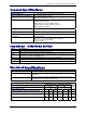
Chapter 1 – Product Description and Specifications General Specifications General Specifications Power Requirements 5 V to 32VDC; 400mA Average @5V, 1A Peak @ 5V Mechanical Dimensions & Weight 4.3" L x 2.4" W x 0.94" H; 4.2 oz. (11 cm x 6.1 cm x 2.4 cm; 119 g) Connectors & Fasteners Antenna Connection type: SMA jack Serial Connector: DE15 Pins: RS232 link, audio link, BOOT, RESET Power Connector: 2.
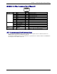
Chapter 1 – Product Description and Specifications RF Specifications Frequency RX Frequency TX RF Power Stand GSM 850 869 to 894 MHz 824 to 849 MHz 2W at 12.5% duty cycle EGSM 900 925 to 960 MHz 880 to 915 MHz 2W at 12.5% duty cycle GSM 1800 1805 to 1800 MHz 1710 to 1785 MHz 1W at 12.5% duty cycle GSM 1900 1930 to 1990 MHz 1850 to 1910 MHz 1W at 12.
Chapter 1 – Product Description and Specifications RS232 15-Pin Connector Pinout 5 10 15 RS-232 Audio Boot Reset PIN 1 6 2 8 9 7 12 11 13 4 5 10 15 3 14 EIA DCD RX TX DTR GND DSR RTS CTS RI MICROPHONE (+) MICROPHONE (-) SPEAKER (+) SPEAKER (-) BOOT RESET 1 6 11 CCIT 109 104 103 108.2 107 105 106 125 Designation Data Carrier Direct Receive Data (out) Transmit Data Data Terminal Ready Signal Ground Data Set Ready Request to Send Clear to Send Ring Indicator For factory use only.
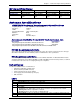
Chapter 2 – Activation and Installation Chapter 2 – Activation and Installation Step 1 – Activate Your Wireless Account Activate Your Wireless Account Please see the wireless account Activation Notices located on the MultiModem CD. Choose the one for your wireless network provider and follow the directions to activate your account. Phone Numbers for the Wireless Modem Every wireless modem will have its own unique phone number.
Chapter 2 – Activation and Installation Step 3 – Hook up the Antenna, Serial Cable, and Power Antenna Connect a suitable antenna to the SMA connector (see antenna specifications on page 9). Antenna Connector (SMA type) Serial Cable Connect both sides of the serial and control cable (15-pin Sub D connector on the modem side). Serial & Control Connector To Serial Port of PC Multi-Tech Systems, Inc.
Chapter 2 – Activation and Installation Power Plug the power supply cable into the modem. For Two-Piece Transformer Power Supply (International). • Connect the AC cord receptacle into the transformer block. • Connect the AC cord plug into the mains power outlet. For One-Piece Transformer Power Supply (North America). • Connect between the MultiModem power receptacle and the mains power outlet. For Optional Direct DC Power • Connect the fused DC power cable into the DC power connector on the modem.
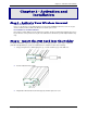
Chapter 2 – Activation and Installation Step 4 – Optional – Attach the Modem to a Flat Surface To mount the Wireless MultiModem, do the following: 1. Obtain mounting screws (two are needed) that are appropriate for the surface on which you will mount the modem. For example, one might use two 6-32 self-tapping screws 5/8” in length to mount the unit in a truck to the wall of the cab behind the passenger’s seat. 2. Typically, the unit is mounted against a flat surface into which holes can be drilled.
Chapter 2 – Activation and Installation Step 5 – Install the Modem Driver Introduction Compatibility: The wireless modem is compatible with Windows 2000/2003+, Windows XP, and Linux. Windows: Windows operating systems require a modem driver to be installed. See the example below for installing a GPRS modem driver onto a PC with Windows XP/2003. Linux: Linux does not require a driver for serial modems.
Chapter 3 – Using Your Wireless Modem Chapter 3 – Using Your Wireless Modem Phone Numbers for the Wireless Modem • Every wireless modem will have its own unique phone number. • The phone number may simply be given to you by your wireless service provider or it may be on the SIM card or both. Wireless provider implementations may vary. Examples of Useful AT Commands A Note About HyperTerminal In order to verify signal strength and roaming status, you must use a terminal application such as HyperTerminal.
Chapter 3 – Using Your Wireless Modem Establishing a Voice Call • Enter PIN Code (if required by your wireless provider) Type AT+CPIN=1234 Responses: OK (PIN Code accepted) +CME ERROR : 16 (Incorrect PIN Code) +CME ERROR : 3 (PIN already entered [with +CMEE : 1 mode]) • Initiate a voice call Type ATD1234; (Note: Don’t forget the semicolon “;” at the end.
Chapter 3 – Using Your Wireless Modem Using Short Message Services (SMS) Send a Short Message to a Specified Number. Type AT+CMGS="8585551212" Then type your message: Please call me soon. The modem may respond with +CMGS: OK Write a Message to Memory. You can store a message to send it at a later date. Type AT+CMGW="8585551212" Type the message. The modem may respond with +CMGW: 4 OK (The message is stored in the index as message 4.
Chapter 3 – Using Your Wireless Modem SMS Examples Send Example Send an SMS message to another SMS compatible device at+cmgf=1 (set to text mode) OK at+cpms="SM","SM" (set memory storage when writing and sending SMS messages) +CPMS: 0,50,0,50 OK at+cmgs="7632273726" (send message to the number specified in quotes) > TEST message ONE.
Chapter 3 – Using Your Wireless Modem Receive Example 3: Receive SMS message in text mode by directly routing the received message to the TE through the serial port using Phase 2+: at+cmgf=1 (set to text mode) OK at+csms=1 (set to Phase 2+) +CSMS: 1,1,1 OK at+cnmi=2,2,0,0,0 (set to receive SMS and route directly to TE) OK +CMT: "+17632273726",,"06/03/17,14:01:17+00" (message received and directly routed to TE) TEST3 at+cnma (acknowledge that message has been received) OK Multi-Tech Systems, Inc.
Chapter 3 – Using Your Wireless Modem Internet Access Internet access can be setup in Windows Dial-Up Networking (DUN) of the computer that the wireless modem is serving. Setup procedures will vary according to the type of wireless service provider used. To access Dial-Up Networking on your PC, go to Start > Settings > Network Connections. • For GSM-without-GPRS, a circuit-switched data connection is used. The user can set up DUN to make a conventional V.
Chapter 3 – Using Your Wireless Modem Create Your Dial-Up Connection in Windows XP/2003 1. Click on Start and then click on Control Panel. 2. In the Control Panel, double-click on Network Connections. 3. On the Network Connections screen on the left-hand side under Network Tasks, click on Create a new connection. 4. The New Connection Wizard should appear. It will walk you through setting up your Internet connection. Click on Next > to begin. 5.
Chapter 4 – Troubleshooting and Frequently Asked Questions Chapter 4 – Troubleshooting and Frequently Asked Questions Troubleshooting Examples Before calling the Multi-Tech Technical Support, check to the following connections: • The right antenna is connected to the modem • The serial cable connection is correct • The power is connected correctly and the power lights on the modem are on • Verify your signal strength • Verify your network registration • Use the following situation examples to troubleshoot
Chapter 4 – Troubleshooting and Frequently Asked Questions Frequently Asked Questions Which providers can I use? • Two major providers are T-Mobile and AT&T. Does this modem support High-Speed Circuit-Switched Data (HSCSD)? • No, our GSM/GPRS modems do not support HSCSD. The modem is answering, but seems to not be doing anything? • The modem is answering in voice mode. • If you are trying to make a data call, make sure the account has CSD service.
Chapter 4 – Troubleshooting and Frequently Asked Questions After changing the +CNMI, +CSCA, or +CSMP command values, the modem doesn’t store them. • When changing these command values, you must use the +CSAS command to store the changes. How do I send an SMS message to an email account? • When sending an SMS message to an email account, you must use a designated routing number that will tell the SMS server to route your message to an email account.
Chapter 5 – Reference Information Chapter 5 – Reference Information Wireless Modem Reference Information Data Cable Diagram – No Voice Multi-Tech Systems, Inc.
Chapter 5 – Reference Information Data Cable Diagram – with Voice Fused DC Power Cable Dimensions How to Change the Fuse The Fused DC power cable is provided when a single unit is purchased. Multi-Tech Systems, Inc.
Appendix A – Warranty and Repairs Appendix A – Warranty and Repairs Multi-Tech Warranty Statement Multi-Tech Systems, Inc., (hereafter “MTS”) warrants that its products will be free from defects in material or workmanship for a period of two, five, or ten years (depending on model) from date of purchase, or if proof of purchase is not provided, two, five, or ten years (depending on model) from date of shipment.
Appendix A – Warranty and Repairs Repair Procedures for International Distributors International distributors should contact their MTS International sales representative for information about the repair of Multi-Tech product(s). Please direct your questions regarding technical matters, product configuration, verification that the product is defective, etc., to our International Technical Support department at +(763)717-5863. When calling the U.S.
Appendix C – China ROHS Appendix B - Waste Electrical and Electronic Equipment (WEEE) Statement July, 2005 The WEEE directive places an obligation on EU-based manufacturers, distributors, retailers and importers to takeback electronics products at the end of their useful life. A sister Directive, ROHS (Restriction of Hazardous Substances) complements the WEEE Directive by banning the presence of specific hazardous substances in the products at the design phase.
Appendix C – China ROHS Appendix C – C-ROHS HT/TS Substance Concentration 依照中国标准的有毒有害物质信息 根据中华人民共和国信息产业部 (MII) 制定的电子信息产品 (EIP) 标准-中华人民共和国《电子信息产品污染控制管理办法》(第 39 号),也称作中国 RoHS,下表列出了 Multi-Tech Systems Inc.