Models MTA128ST and MTA128NT External ISDN Terminal Adapter User Guide
User Guide Model MTA128ST/NT S000305B Rev. B This publication may not be reproduced, in whole or in part, without prior written permission from Multi-Tech Systems, Inc. All rights reserved. Copyright © 2004 by Multi-Tech Systems, Inc. Multi-Tech Systems, Inc. makes no representations or warranties with respect to the contents hereof and specifically disclaims any implied warranties of merchantability or fitness for any particular purpose. Furthermore, MultiTech Systems, Inc.
Cont ents ontents Chapter 1: Introduction and Description ..................................................................................................................... 4 Welcome to the world of ISDN communications. .............................................................................................................. 4 Product Description ..........................................................................................................................................................
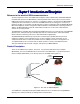
Introduction and Description Chapt er 1: Intr tion and DDescription escription hapter Introoduc duction Welcome to the world of ISDN communications. You have acquired one of the finest ISDN terminal adapters (TAs) available today, model MTA128ST/NT from Multi-Tech Systems. The MTA128ST is a desktop TA with an S/T interface port to connect it to the ISDN network and an analog port to connect it to a telephone, modem, or fax machine.
Introduction and Description This manual documents the following models: • MTA128ST for S/T interface with one POTS port • MTA128NT for U interface with one POTS port Some analog devices, including telephone set, answering machine, and modem, can be connected to the POTS port via an RJ-11 jack. This User Guide will help you install, configure, and operate your terminal adapter. Features The MTA128ST/NT communicates over public ISDN telephone lines.
Introduction and Description If your ISDN product operates with a S/T outlet interface, you need an NT1 device to connect to the ISDN switch. MTA128ST adapters need an NT1 device to connect to the ISDN switch, but the MTA128NT adapter does not require NT1 device. In the UK, and in many European countries, NT1 device is supplied by your telephone company.
Introduction and Description U Interface The U interface uses a 2-conductor twisted pair cable terminated with an RJ-45 jack. An RJ-45 jack located on the terminal is used to connect the terminal to the Digital Subscriber Loops using this twisted pair cable. In Table 2-2 the Pin Number, Terminal Pin Signal Name and UILC Pin Signal Names for the U interface are listed.
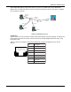
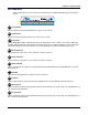
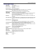
Introduction and Description LED Indicators The ten LED indicators on the front panel (see figure below) of the MTA128ST/NT report status and line activity. TD Transmit Data Flashes when data is being transmitted (on for a space, off for a mark). RD Receive Data Flashes when data is being received (on for a space, off for a mark). LS Link Status For EuroISDN NET3, INS64, and VN4 switch protocols, lights when the TA is turned on.
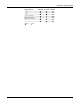
Introduction and Description Data Protocol 128 LED P1 LED P2 LED V.110 V.120 X.
Introduction and Description Technical Specifications Trade Name Model Number IWay Hopper™ MTA128ST (International), MTA128NT Network Interface ST-Four-wire S/T interface NT– 2-wire “U” interface Switch Compatibility EuroISDN (ETSI/DSS1/NET3), VN4, INS64, U.S. NI-1, AT&T 5ESS, DMS-100 (both models support all of the switch protocols) B-Channel Protocols V.110 (some models only),V.120, X.
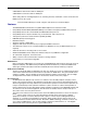
Hardware Installation Chapt er 2: Har dw ar hapter Hardw dwar aree Installation This chapter shows you step-by-step how to set up your MTA128ST/NT terminal adapter (TA) to your computer, power, network terminator, and an auxiliary analog device. Please follow these instructions carefully to avoid damage to your TA . Safety Warnings • Use this product only with UL-listed and CUL-listed computers. • Never install phone wiring during a lightning storm.
Hardware Installation Connect the TA to the AC Power Outlet Plug the DC power transformer into an AC power outlet or power strip. Plug the DC power transformer into the POWER jack on the TA. Note: Use only the DC power transformer supplied with the TA. Use of any other transformer voids the warranty and can damage the TA. Turn on the TA by sliding the power switch to ON and verify operation by observing the LEDs on the front panel. The LEDs first flash in a self-test pattern. Then the LS LED remains on.
Configuration Utilities Chapt er 3: CConf onf igur ation Utilities hapter onfigur iguration Introduction You can configure the MTA128ST/NT to match your ISDN service and the remote terminal adapter (TA) with any of four methods listed below: • ISDN TA Configuration Utility This configuration utility is recommended for computers running Windows 98/NT/ME operating systems. Because it is a software-based utility, you can use it to create and store as many configurations as you want.
Configuration Utilities The Data MSN (multiple subscriber number) allows a caller to specify an individual TA when more than one TA is connected to you network terminator. If you don’t assign a value to the MSN, the TA accepts all incoming calls. If you only assign a base address to the MSN, the TA accepts any incoming call with the same base address, regardless of whether a subaddress is included.
Configuration Utilities V.120 Protocol—Similar to V.110 protocol, but provides rates up to 64000 bps on each B channel. X.75 Protocol—Packet-switched network protocol for international use. Layer 2 portion of this protocol is used commonly as a rate adaption protocol. MLPPP Protocol—MLPPP (Multi-Link PPP) protocol provides rates up to 64 Kbps per channel. This protocol uses both B channels at once, providing an aggregate data transmission speed of 128 Kbps.
Configuration Utilities DTR Control _________________________________ A high DTR (Data Terminal Ready) signal on the RS232 serial port indicates your computer or terminal is ready to communicate with your TA. It normally goes high when a communication program starts or is ready to dial. Normal causes the TA to break the link and go into command mode when DTR drops. Ignore causes the TA to ignore the DTR signal. Reset on DTR causes the TA to reset when DTR drops for the time specified in register S25.
Configuration Utilities Configuring your TA If you use Windows 98/Me/NT, perform the following procedure using the Configuration Utility provided on your system CD. If you are using another operating system, you can configure the TA using the firmwarebased configuration utility or AT commands. Procedures for using the firmware-based configuration utility and AT commands are described in Appendix E.
Configuration Utilities 3. Searching for TA screen is displayed with please wait while the configuration utility searches for your ISDN TA(s). This may take up to 20 seconds. Then the Searching for TA screen with Devices have been identified. Please select a device to configure Click Next to continue. 4. The Configuration screen is displayed with Select the type of setup, custom building a new configuration, custom with an existing configuration, or express with an existing configuration.
Configuration Utilities 5. The Network Switch Type screen is displayed with Please select the settings for the Network Switch Type. Select the network switch type you listed in the Before You Start section of this chapter. 6. Please select the settings for dynamic bandwidth allocation, high and low sampling period and throughput, and call bumping. Click Next to continue.
Configuration Utilities 7. The TEI (Terminal Endpoint Identifier) screen is displayed with Please select the settings you would like for Data TEI and Voice TEI. The TEI is a unique number assigned to the TA at subscription time. The TEI is used by the telephone central office (CO) to identify the various TAs connected to the ISDN network. The TEI number can be fixed (range 0 - 63) or dynamic and is assigned automatically at the CO each time the TA connects to the ISDN interface and powers up.
Configuration Utilities SPID is only used in North America. A SPID is the ISDN network parameter for local terminal identification and tracking. A SPID is assigned by your local ISDN provider when you subscribe, they are in the form of a string of up to 20 characters. A SPID points to a specific location in the provider’s central office memory where service and feature parameters are stored. Click Next when you have entered your SPID information. 9.
Configuration Utilities 10. The Data Protocol Setup screen is displayed with Please select the setting you desire for the Data Protocol. If you would like the TA to detect the data protocol of an incoming data call and automatically change the TA’s protocol to match the incoming call, click auto protocol detection check box. Click Next to continue. 11. The Stored Numbers screen is displayed with Please enter the numbers you would like to store.
Configuration Utilities 12. The Port Control Setup 1 screen is displayed with Please select the settings you would like for the DTR detect time, DCD drop time, DTR, DSR, CTS, and DCD signals. Click Next when you have finished entering your settings. 13. The Port Control Setup II screen is displayed with Please select the settings you would like for the Default Parity, Default Bit Rate, number of Data Bits, number of Stop Bits, Flow Control, and synchronous mode. Click Next when you are finished.
Configuration Utilities 14. The POTS Port screen is displayed with Please select the settings for the PORTS port. When your selections are complete, click Next. 15. The Save Configuration screen is displayed with Please enter the name to store the configuration as in the .ini file. You can enter any name up to 35 characters or less in the Store Configuration as: window. Click Next after you have selected a name.
Configuration Utilities 16. The Load Configuration screen is displayed with To load the configuration now, click Next. 17. Your ISDN TA is currently being configured. When the Finish button becomes active, click Finish. 18. The Configured screen is displayed. Click Finish to exit the Configuration Utility.
AT Commands, S-Registers, and Result Codes Chapt er 4: AATT CCommands, ommands, S-R egist ers, and RResult esult CCoodes hapter S-Regist egisters, MTA128ST/NT Commands and S-Registers All references to “TA” in this chapter refer to the MTA128ST/NT. This chapter also assumes knowledge of issuing AT commands. refers to the carriage return character (typically generated by pressing the ENTER or RETURN key on the keyboard). For command execution details see the additional documents on this CD.
AT Commands, S-Registers, and Result Codes AT A/ Return or Enter +++AT AT Attention code Repeat AT Command Command execution In-band escape code Out-of-band escape code General Information Commands In Display Product Information Ln List Active Profile Information !L Display Network Configuration >MIBn Management Information Block (MIB) Information Network Configuration Commands **s User-User Information Element String %A97=n Dialing Method >A0=n Type of Coding !C0=n Network Switch Type !C6
AT Commands, S-Registers, and Result Codes En %En &Fn %Mn Qn Sr=n Sr? Vn &Wn Xn Z &Zn= !Z=n Command Mode Echo Escape Sequence Options Load Factory Profile Management Mode Quiet Mode Set S-register Read S-register Verbose Result Codes Store Active Profile Connect Messages Reset to Stored Profile Store Telephone Number Rate Adaptation/Data Protocol Digital (Data) Call Commands A Answer Digital Call Dn Dial Digital Number DSn Dial Stored Number Hn Hang up Digital Call !Hn Digital Call Hold-off Time &Jn Chan
AT Commands, S-Registers, and Result Codes S-Registers S-registers are sections of memory in which values are stored that affect how the TA operates. S-registers are so-called because each has a name that begins with the character S. Use the Sr=n command to assign a value to an S-register or use the Sr? command to read the current value of an S-register. Sregisters are stored in non-volatile RAM (NVRAM) by using the &W0 command.
AT Commands, S-Registers, and Result Codes S63 S64 S65 S66 S67 S68 S69 S70 S71 S73 S74 S75 S76 S77 S80 S81 S82 S84 S85 S86 S87 S154 MTA128ST/NT Bandwidth-On-Demand (BOD) Low Throughput Threshold Call Bumping (CB) POTS Call Bump Forwarding Delay Country Selections for POTS Ring Signal Single or Dual Cadence POTS Ring Signal POTS Ring Signal First Active Duration POTS Ring Signal First Idle Duration POTS Ring Signal Second Active Duration POTS Ring Signal Second Idle Duration MultiLink Endpoint Discriminat
AT Commands, S-Registers, and Result Codes Result Codes When the MTA128ST/NT receives an AT command from the computer or terminal, it attempts to execute the command, then sends a status message to the computer or terminal that reports the result of the command. The MTA128ST/NT provides you with several of these response messages, or result codes, which can be displayed on your monitor or intercepted and used by your communications software.
AT Commands, S-Registers, and Result Codes • Data Mode—MTA128ST/NT enters data mode when it makes a successful data communications link with a remote device. In data mode, the TA can send and receive data, but it does not respond to AT commands. Instead it treats them as data and transmits them to the remote device. • Online Command Mode—MTA128ST/NT responds to AT commands while maintaining a data communications link; however, transmission of data is suspended.
AT Commands, S-Registers, and Result Codes Displaying a Stored Number To display a stored telephone number, type &Zn? in terminal mode, where n is the memory register in which the number is stored. For example, type AT&Z5? to display the telephone number in memory register 5. To list all ten telephone numbers stored in memory, type ATL . Answering a Call You can answer incoming calls to the MTA128ST/NT either manually or automatically.
Troubleshooting Chapt er 5: TTrroublesho oting hapter oubleshooting Troubleshooting the TA Introduction This chapter describes basic problems you may run into with your MTA128ST/NT and how to solve them. Your MTA128ST/NT was thoroughly tested at the factory before it was shipped. If you are unable to make a successful connection, or if you experience data loss during your connection, it is possible that the MTA128ST/NT is defective. However, it is more likely that the source of your problem lies elsewhere.
Troubleshooting SITUATION 4: The autobauding code does not report the number of stop bits. This may become a problem if the terminal is expecting a certain number of stop bits. The addition of the %S3 command and use of $SBn, @P3=n, @P4=n, and @P6=n will help work around this limitation. See the description for the %Sn command. Debugging/Logging/Troubleshooting Commands The AT commands in this section can be used in attempting to troubleshoot or debug a current problem.
Troubleshooting None of the LEDs light when the MTA128ST/NT is on When you turn on the MTA128ST/NT, the LED indicators on the front panel should flash briefly as the TA runs a self-test. If the LEDs remain off, the TA probably is not receiving power. • Make sure the MTA128ST/NT’s power switch is on, especially if you normally turn on the TA by turning on a power strip. • If the power supply is plugged into a power strip, make sure the power strip is plugged in and its power switch is on.
Troubleshooting • Is this the first time you have used the cable? If so, check the cable description on the packaging to make sure the cable is correct for your computer. • Peripheral expansion cards, such as bus mouse and sound cards, may include a serial port preconfigured as COM1 or COM2. The extra serial port, or the card itself, may use the same COM port, memory address, or interrupt request (IRQ) as your communications port. Be sure to disable any unused ports.
Troubleshooting • If the MTA128ST/NT reports NO DIALTONE, check that the ISDN S/T cable is securely connected to both the TA’s ISDN jack (not the PHONE jack) and the ISDN network terminator or wall jack. If the cable looks secure, try replacing it. If that doesn’t work, the problem may be in your building’s telephone installation. Make sure ISDN cables on all devices are wired straight-through (pin 1 to pin 1, pin 2 to pin 2, etc.) and do not have reversed pairs.
Troubleshooting File transfer appears slower than it should be • If you have a Universal Asynchronous Receiver/Transmitter (UART) that is compromising data throughputs, we recommend replacing it with a special I/O card. • If you are running under Windows 3.1 and have a 16550AFN UART, replace the Windows serial driver, COMM.DRV, to take full advantage of the UART’s speed. • Check the serial port baud rate in your communications software, and make sure it is set as high as your UART allows.
Troubleshooting The MTA128ST/NT receives garbage characters after receiving several good characters when connected to a 3Com Sonix adapter. Most likely, the Sonix has compression turned on. The compression used by the Sonix is incompatible with the compression used by the MTA128ST/NT. Disconnect the data connection and the give the Sonix the command AT”HO (that’s a double quote) and then establish the data connection again. The garbage characters should disappear.
PPP/MLPPP Chapt er 6: PPoint-t oint-t o-P oint CCommunic ommunic ations: PPP/MLPPP hapter oint-to-P o-Point ommunications: Bonding Using the &, ! and + Characters You can use the &, ! and + characters to bond two channels together when performing channel bonding (available only with the MLPPP protocol). When you use the &, +, or ! characters with the MLPPP protocol, the TA regards the number following that character as a second phone number.
PPP/MLPPP If throughput drops below a given threshold, the second channel is removed to save the cost of having the second B-channel active but not fully used. If an outgoing analog call is desired or there is an incoming analog call, a data channel can be bumped (removed) to allow analog POTS port use. Bandwidth-on-Demand (BOD) checks the data throughput to determine whether a channel should be added or removed.
PPP/MLPPP • Ideally, the second channel should be added quickly (short High Threshold Sampling Period [S60] with a relatively small High Throughput Threshold [S61] ). Also, the second channel should not be disconnected for a relatively long period of time (long Low Threshold Sampling Period [S62] with a small Low Throughput Threshold [S63] ).
Warranty, Service, and Technical Support Chapt er 7: W arr ant er vic e, and TTech ech SSupp upp or hapter Warr arrant antyy, SSer ervic vice, uppor ortt Multi-Tech Systems, Inc. Warranty & Repairs Policies Warranty Multi-Tech Systems, Inc.
Warranty, Service, and Technical Support Repair Procedures for International Customers (Outside U.S.A. and Canada) Your original point of purchase Reseller may offer the quickest and most economical repair option for your Multi-Tech product. You may also contact any Multi-Tech sales office for information about the nearest distributor or other repair service for your Multi-Tech product. http://www.multitech.com/COMPANY/offices/DEFAULT.
Warranty, Service, and Technical Support Please direct your questions regarding technical matters, product configuration, verification that the product is defective, etc., to our Technical Support department at 800 972-2439 or e-mail tsupport@multitech.com. Please direct your questions regarding repair expediting, receiving, shipping, billing, etc., to our Repair Accounting department at 800 328-9717 or +763 785-3500, or e-mail mtsrepair@multitech.com.
Warranty, Service, and Technical Support Technical Support Multi-Tech Systems has an excellent staff of technical support personnel available to help you get the most out of your Multi-Tech product. If you have any questions about the operation of this unit, please call 800 972-2439 (USA and Canada) or 763 785-3500 (international and local). Please have modem information available.
Appendices App endix A:C onf igur ation PPrrof iles Appendix A:Conf onfigur iguration ofiles Quick Setup Factory Profiles For quick setup, the MTA128ST/NT includes six Quick Setup Factory Profiles, each of which is configured for a specific type of port operation. You can load a Quick Setup Factory Profile into active memory by using the command &Fn, in which n is the number of the profile you wish to load.
Appendices App endix B: Or dering YYour our ISDN LLine ine Appendix Ordering There are two ways to specify your ISDN line configuration to your service provider. One is by using ISDN "ordering codes" in which the user, the Local Exchange Carrier (LEC) or Internet Service Provider (ISP) are using common nomenclature to describe elements of service.
Appendices Bearer Service The options of Circuit Switch Voice Bearer (CSV) and Circuit Switch Data Bearer (CSD) are broad categories of Bearer Services that the phone companies can provide. Different bearer services provide different types of guarantees about the reliability and synchronization of the data. There are currently ten different bearer services for circuit-mode, and three services for packet mode.
Appendices I2 (previously "Generic Data I-1DN") This ISDN ordering code supports: • 2B Service, • Data only on each B channel, and • One directory number. I2 is not available on the Northern Telecom switch. Two directory numbers are required for 2B operation; in this case use J2. J2 (previously "Generic Data J") This ISDN ordering code supports: • 2B Service, • alternate voice and data on one B channel, data only on other B channel, and • Two directory numbers.
Appendices Ordering ISDN Without IOCs This section guides you and your telephone company in specifying and obtaining ISDN service when IOCs are not used. To support most ISDN TA features, your telephone service must meet certain requirements. These requirements are described in the following sections. Some features may be added or deleted, depending on your actual data service needs and availability in your area.
Appendices Turn these features OFF: Packet Mode Data MultiLine Hunt Multiple Call Appearances EKTS (Electronic Key Telephone Sets) Shared Directory Numbers Accept Special Type of Number Intercom Groups Modem Pools (Network Resource Selector) Message Waiting Hunting InterLATA Competition 5b.
Appendices The requirements for the 5ESS line are shown below: B1 Service: DMD (On-demand) B2 Service: DMD (On-demand) Data Class Line: PM (Point-to-MultiPoint) Max. B Channels: 2 Number of CSV Calls: 2 CSV Bearer Channels: Any Number of CSD Calls: 2 Circuit Switched: Any Terminal Type Bearer Channels: Type A Multipoint lines require the phone company to create a SPID for each phone number on the line.
Appendices Line Type: Basic rate, functional EKTS: No CACH: No Initializing terminal: Yes Bearer services: Circuit-switched voice & data permitted (Packet mode data not permitted) Circuitswitched service: Yes Packet-switched service: No Protocol version: Functional Pvc1 TEI: Dynamic MTA128ST/NT 55
Appendices App endix C: FC anadian RRegulation egulation Appendix FCCC and CCanadian FCC 1. This equipment complies with Part 68 of the Federal Communications Commission (FCC) rules. On the outside surface of this equipment is a label that contains, among other information, the FCC registration number and ringer equivalence number (REN). If requested, this information must be provided to the telephone company. 2.
Appendices Canadian Limitations Notice Notice: The ringer equivalence number (REN) assigned to each terminal device provides an indication of the maximum number of terminals allowed to be connected to a telephone interface. The termination of a interface may consist of any combination of devices subject only to the requirement that the sum of the ringer equivalence numbers of all the devices does not exceed 5. Notice: The Industry Canada label identifies certificated equipment.
Appendices App endix D: CConf onf igur ation Metho ds Appendix onfigur iguration Methods Firmware-based Configuration Utility 1. If you are using another operating system, turn on your computer and start your data communications program. 2. The TR (Terminal Ready) LED lights to indicate that your computer is ready to communicate with the TA. Type AT in the communications program’s terminal window and press ENTER. The TA should respond with OK. If it doesn’t, go to Chapter 5 for troubleshooting help. 3.
Glossary Glos sar Glossar saryy Symbol 2B1Q (2 bits, 1 quarternary)—A line code at layer one for the BRI U interface. Two bits of data (2B) are mapped into one of four line values (1Q, or 1quarternary). This coding scheme allows a single copper pair to carry 160 Kbps of information bidirectionally and simultaneously at a distance of up to three miles. A ACK (acknowledgement code)—A communications code sent from a receiving modem to a transmitting modem to indicate that it is ready to accept data.
Glossary bus—A common channel between hardware devices, either internally between components in a computer, or externally between stations in a communications network. byte—A unit of information consisting of eight binary digits (bits). A byte holds the equivalent of a single or character (such as the letter A). office. D-channel—A non-ransparent digital ISDN channel that operates at 16K or 64 Kbps, used for call control signalling, along with one or more Bchannels.
Glossary been approved by a regulatory group. exchange area—A geographical area with a uniform set of charges (tariffs), approved by a regulatory group for telephone services. Calls between any two points within an exchange area are local calls. See digital PBX and PBX. university, government, and private users around the world. Internet address—A unique 32-bit address for a specific TCP/IP host on a network. Normally printed in dotted decimal format (e.g., 129.128.44.227).
Glossary compressed in a secure manner before being encrypted with a private (secret) key under public-key cryptisystem. MLPPP (Multilink Point-to-Point Protocol, also the PPP Multilink Protocol or MP)—is an Internet standards track protocol for a methyod of splittingm recombining, and sequencing datagrams across multiple logical data links, giving you additional bandwithon-demand.
Glossary services. Also called the S-interface. (Contrast R-reference point.) SAP (service access point)—A point at which the services of an OSI layer are made available to the next higher layer. See also SAPI. SAPI (service access point identifier)—A logical point at which data link layer services are provided by a data link layer entity to a layer 3 entity. See also SAP.
Glossary data to it at 56 Kbps. It is a relatively low cost service, widely used in North America for telecommuting, videoconferencing and high speed data transfers. Many phone companies are phasing out switched 56 in favor of ISDN service. switched line—In communications, a physical channel established by dynamically connecting one or more discreet segments. This connection lasts for the duration of the call after which each segment may be used as part of a different channel. Contrast with leased line.
Index Index A answering a call manually 33 Appendix A:Configuration Profiles 48 Appendix C: Ordering Your ISDN Line 49 ISDN, ordering 49 Appendix D: FCC and Canadian Regulation FCC Canadian Regulation 56 Appendix E: Configuration Methods Configuration Methods 58 async data format 10 AT commands !C0= 13 &F 48 &W 48 &Zn= 32 &Zn? 33 +++AT 32 A 33 D 32 H 33 L 33 lack of response to 36 O 32 V 31 AT commmands using to configure the TA 13 autoanswer 33, 38 B B-channel protocol 10 Bandwidth on Demand baud
Index ISDN line 37 ISDN, ordering 49 ISDN Solutions Group 50 ISDN TA Configuration utility S S-registers S0 33, 38 safety 11 serial port 10, 32, 36, 37, 39 service profile idenfiier (SPID) 14 setup 48 specifications technical 9 speed serial port 32 SPID (service profile identifier) 14 stop bits 15 storing telephone number 32 support, technical 47 switch type 10 13 L LED Indicators Link Status 8 LED indicators 10, 36 128 Kbps 8 Bearer Channel 1 8 Bearer Channel 2 8 Data Protocol 8 Link Status 8 Off Hook 8