MultiModemZBA Global MT5634ZBA-Series MT5634ZBA–V.90 MT5634ZBA-V–V.90 MT5634ZBA–V.92 MT5634ZBA-V–V.
MultiModemZBA Global MT5634ZBA-Series User Guide MT5634ZBA–V.90, MT5634ZBA-V–V.90, MT5634ZBA–V.92, MT5634ZBA-V–V.92 PN S000286A, Version A Copyright This publication may not be reproduced, in whole or in part, without prior expressed written permission from Multi-Tech Systems, Inc. All rights reserved. Copyright © 2003, by Multi-Tech Systems, Inc. Multi-Tech Systems, Inc.
Table of Contents Table of Contents Chapter 1 - Introduction................................................................................................................................5 The Products ............................................................................................................................................5 The Features ............................................................................................................................................
Table of Contents Appendix C - Regulatory Compliance.......................................................................................................35 FCC Part 15 Regulation .........................................................................................................................35 FCC Part 68 Telecom.............................................................................................................................36 Fax Branding Statement.....................................
Chapter 1 - Introduction Chapter 1 - Introduction Congratulations on your purchase of the MultiModemZBA modem. You have acquired one of the finest intelligent voice/data/fax modems available today from one of the world’s oldest modem manufacturers: Multi-Tech Systems, Inc. This user guide will help you to install, configure, test and use your modem. The Products MT5634ZBA-V.90 MT5634ZBA-V-V.90 MT5634ZBA-V92 MT5634ZBA-V-V92 A desktop global data/fax modem supporting the V.90 protocol.
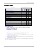
Chapter 1 - Introduction Features Table PRODUCTS FEATURES MT5634 ZBA V.90 V.90/56K Max. Data Speed V.92/56K Max. Data Speed Modem-on-Hold (V.92 Feature) Global Approval in Many Countries for Worldwide Use Voice Support Callback Security 2-Wire Leased-Line Support DTMF Tone Detection Phone Number Storage for Automatic or DTR Dialing Common Features: · V.90 or V.92 Related Features (see below) · Remote Configuration · Error Correction · Caller ID (U.S.
Chapter 1 - Introduction What Is in Your Modem Package · An MT5634ZBA-Series modem · A set of four self-adhesive plastic feet · This Quick Start Guide · A system CD containing modem drivers, a User Guide, an AT Command Reference Guide, PhoneTools (a data communications program), and Acrobat Reader. · A universal power supply · A 9-pin to 25-pin serial cable · An RJ-11 phone cable · A power cord (country-specific) Multi-Tech Systems, Inc.
Chapter 2 - Installation Chapter 2 - Installation This chapter shows you step-by-step how to set up your Multi-Tech MT5634ZBA modem. Safety Warnings · · · · · · · · Use this product only with UL- and CUL-listed computers (U.S.A. and Canada) To reduce the risk of fire, use only 26 AWG (.41mm) or larger telephone wiring. Never install telephone wiring during a lightning storm. Never install a telephone jack in a wet location unless the jack is specifically designed for wet locations.
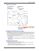
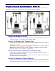
Chapter 2 - Installation Location of the Jumpers Jumper for Modem with Voice Option Changing the Dial-Up/Leased-Line Jumper As shipped from the factory, your modem is configured for normal dial-up operation. That is, the modem must dial a phone number to connect to another modem. To use the modem on a leased line, you must change jumper J10 to select leased line operation, and J11 to select whether it will be the originating or the answering modem. If dial-up operation is selected, J11 has no effect.
Chapter 2 - Installation Step 3: Connect the Modem to Your PC Turn off your computer. Place the modem in a convenient location, and then connect it to your computer’s serial port, the telephone line or leased line, AC power, and, optionally, your telephone. Connections - No Voice Connections With Voice Connect the Modem to Your PC Plug one end of the serial cable into the RS232 connector on the modem and the other end into a serial port connector on your computer, such as COM1 or COM2.
Chapter 2 - Installation Connect a Microphone (Voice Option) For voice mail or speakerphone applications, plug an unamplified microphone into the MIC jack on the side of the modem. The microphone should have a stereo 1/8-inch mini plug. Do not use a monophonic microphone. Connect Speakers (Voice Option) For speakerphone or voice mail applications, use a 1/8-inch plug male-to-male stereo patch cord to connect the SPKR jack on the side of the modem to the LINE IN jack on your sound card.
Chapter 2 - Installation Step 4: Install the Modem Driver If you use Windows 95 or above, you must install the modem driver. The modem driver tells Windows how to control the modem. If you use a Linux operating system, please see Appendix D. If you use another operating system, please refer to its documentation for modem installation information. Installing the Modem Driver 1. Make sure your modem is connected properly, and then turn on your computer.
Chapter 2 - Installation Step 5: Configure the Modem for Your Country Different countries have different requirements for how modems must function. Therefore, before you use your modem, you must configure it to match the defaults of the country in which you are using it. You must also do this if you move the modem to another country after it has been configured for the first country. You can use one of two configuration methods: 1. Use the Global Wizard to Configure Your Modem 2.
Chapter 2 - Installation Step 6: Install Data Communications Software Data communications software is designed to configure a modem so it can send and receive messages. Your Multi-Tech modem operates under the control of a data communications program, such as Phone Tools, included with the modem. The modem can also operate under other general-purpose data communication programs, such as Windows HyperTerminal.
Chapter 3 - Operation Chapter 3 - Operation About the Front Panel The MultiModem V.92 Front Panel The MultiModem V.90 Front Panel The MultiModemZBA LED indicators on the front panel indicate status, configuration, and activity: TD – Transmit Data. Flashes when the modem is transmitting data to another modem. RD – Receive Data. Flashes when the modem is receiving data. CD – Carrier Detect. Lights when the modem detects a valid carrier signal from another modem.
Chapter 3 - Operation PhoneTools Features With the PhoneTools communications program included with your modem, you can: · Upload and download data files. · Send faxes at preset times. · Store incoming voice messages and faxes. · Retrieve stored messages, faxes, and telephone numbers (telephone number retrieval requires Caller ID service from your telephone company). · Print a received fax.
Chapter 3 - Operation · Modem-on-Hold. Modem-on-Hold enables you to put a V.92-capable server on hold while you take another call. Modem-on-Hold operation is possible only with the Modem-on-Hold program included with the MT5634ZBA modem. Connecting to the Internet Your Multi-Tech modem is your gateway to the Internet and the World Wide Web. To access the Internet and Web via your modem, you must establish a dial-up account with an Internet service provider (ISP).
Chapter 4 - AT Commands, S-Registers, and Result Codes Chapter 4 - AT Commands, SRegisters, and Result Codes The AT Commands, S-Registers, and Result Codes for the MT5634ZBA-Series Modems are published is a separate Reference Guide. This guide is included on the MT5634ZBA-Series system CD. You can open the guide from the CD, or you download the guide to your hard drive. Multi-Tech Systems, Inc.
Chapter 5 - Remote Configuration Chapter 5 - Remote Configuration Remote configuration is a network management tool that allows you to configure MT5634ZBA modems anywhere in your network from one location. With password-protected remote configuration, you can issue AT commands to a remote modem for maintenance or troubleshooting as if you were on site. Basic Procedure The following steps can be used when the connection is established by the local or the remote modem.
Chapter 6 - Callback Security Chapter 6 - Callback Security This chapter describes how to use callback security with your modem. Callback security protects your network from unauthorized access and helps control long-distance costs. When callback security is enabled, all callers are requested to enter a password. If a valid password is received, the modem hangs up and returns the call by dialing a phone number that is stored with the password.
Chapter 6 - Callback Security is asked to enter the password again before a connection can be made. Also, dialing command locations 0–3 for use with the DS=y dialing command are replaced by callback dialing command locations 0–29. · To temporarily disable callback security if the modem is set to #CBS1 or #CBS2 (for instance, to call another modem): Type AT#CBS3 and press ENTER. The modem returns to its original setting when you issue the hangup command (+++ATH) or the modem is reset.
Chapter 6 - Callback Security Calling Procedures Use the following procedures to call a modem that has callback security enabled. Note that Autoanswer must be enabled on the calling modem (S0=1). Password-Only Callback Use this procedure when calling from a fixed location. 1. Using a data communications program such as HyperTerminal or PhoneTools, dial the number of the callback modem. 2. When the connection is established, the callback modem responds with the following message: Password> 3.
Chapter 6 - Callback Security Extension-Entry Callback Use this procedure when calling from an extension at the callback number. The password that you use must be set up for an optional extension-entry callback. 1. Using a data communications program such as HyperTerminal or PhoneTools, dial the number of the callback modem. 2. When the connection is established, the callback modem responds with the following message: Password> 3.
Chapter 6 - Callback Security Callback Assignments Form Location Password Telephone Number 0 1 2 3 4 5 6 7 8 9 10 11 12 13 14 15 16 17 18 19 20 21 22 23 34 25 26 27 28 29 Multi-Tech Systems, Inc.
Chapter 7 - Troubleshooting Chapter 7 - Troubleshooting Your modem was thoroughly tested at the factory before it was shipped. If you are unable to make a successful connection, or if you experience data loss or garbled characters during your connection, it is possible that the modem is defective. However, it is more likely that the source of your problem lies elsewhere. The following symptoms are typical of problems you might encounter: · None of the LEDs light when the modem is on.
Chapter 7 - Troubleshooting · · · · · · · · Try resetting your modem by turning it off and on. If you are using DOS or Windows 3.1 communication software, make sure the initialization string includes &F as the first command, to cancel any “leftover’ command that could affect the modem’s operation. If you don’t get an OK, the problem may still be in the communication software. Make sure you have done whatever is necessary in your software to make a port connection.
Chapter 7 - Troubleshooting You can narrow the list of possibilities by using extended result codes. Extended result codes are enabled by default. If they have been disabled, include V1X4 in the modem’s initialization string, or in terminal mode enter ATV1X4 and press ENTER. When you dial again, the modem reports the call’s progress. Multi-Tech Systems, Inc.
Chapter 7 - Troubleshooting · · · · · If the modem reports NO DIALTONE, check that the modem’s telephone line cable is connected to both the modem’s LINE jack (not the PHONE jack) and the telephone wall jack. If the cable looks secure, try replacing it. If that doesn’t work, the problem might be in your building’s telephone installation. To test the building installation, plug a telephone into your modem’s telephone wall jack and listen for a dial tone.
Chapter 7 - Troubleshooting Modem Cannot Connect When Answering · · The default DTR Control command (&D2) inhibits autoanswer. To enable autoanswer, change DTR Control to &D0, and make sure &Q0, &Q5, or &Q6 is also set. For more information, see the &D command in the AT Commands Reference Guide. For information on changing the modem’s default configuration, see “Install and Configure Your Software” in Chapter 2. Autoanswer might be disabled.
Chapter 7 - Troubleshooting The Modem Doesn’t Work with Caller ID · · Caller ID information is transmitted between the first and second rings, so if autoanswer is turned off (S0=0) or if the modem is set to answer after only one ring (S0=1), the modem will not receive Caller ID information. Check your initialization string, and if necessary change it to set the modem to answer after the second ring (S0=2). Make sure that you have Caller ID service from your telephone company.
Appendix A - Technical Specifications Appendix A - Technical Specifications The MT5634ZBA-Series modem meets the following specifications: Trade Name MultiModemZBA™ Model Number MT5634ZBA Build Number Global MT5634ZBA–V90, Global MT5634ZBA-V–V90, Global MT5634ZBA–V92, Global MT5634ZBA-V–V92 Server-to-Client Data Rates 56K speeds when accessing a V.90 or V.92 server (actual speed depends on server capabilities and line conditions)* Client-to-Server Data Rates Up to 48Kbps when accessing a V.
Appendix A - Technical Specifications Transmit Level -11 dBm (North America) – varies by country setting Frequency Stability ±0.01% Receiver Sensitivity -43 dBm under worst-case conditions AGC Dynamic Range 43 dB Interface TIA/EIA RS-232C/ITU-T V.24/V.28 Connectors DB25F RS-232C connector; 2 RJ-11 telephone jacks; power jack Cables Country-specific telephone; power cables; serial cable Note: Any cables connected to the computer should be shielded to reduce interference.
Appendix B - Upgrading the Modem’s Firmware Appendix B - Upgrading the Modem’s Firmware Your modem is controlled by semi-permanent software, called firmware, which is stored in flash memory. Firmware is nonvolatile; that is, it remains stored in memory when the modem is turned off. However, it can be changed by either the manufacturer or the user as bugs are fixed or new features are added.
Appendix B - Upgrading the Modem’s Firmware Step 3: Download the Upgrade File 1. If you are not already at the MultiModemZBA Firmware page of the Multi-Tech Web site, follow the procedure in “Step 2: Identify the Current Firmware.” 2. Download the upgrade file for your modem by clicking its name, and save the file in a temporary folder on your hard disk. 3. In the same section of the Web page, click the Flash Wizard utility for your operating system to download it, and save it in the same folder.
Appendix C - Regulatory Compliance Appendix C - Regulatory Compliance FCC Part 15 Regulation This equipment has been tested and found to comply with the limits for a Class B digital device, pursuant to Part 15 of the FCC rules. These limits are designed to provide reasonable protection against harmful interference in a residential installation.
Appendix C - Regulatory Compliance FCC Part 68 Telecom 1. This equipment complies with Part 68 of the Federal Communications Commission Rules. On the outside surface of this equipment is a label that contains, among other information, the FCC registration number. This information must be provided to the telephone company. 2. The suitable USOC jack (Universal Service Order Code connecting arrangement) for this equipment is shown below.
Appendix C - Regulatory Compliance Fax Branding Statement The Telephone Consumer Protection Act of 1991 makes it unlawful for any person to use a computer or other electronic device, including fax machines, to send any message unless such message clearly contains the following information: · Date and time the message is sent · Identification of the business or other entity, or other individual sending the message · Telephone number of the sending machine or such business, other entity, or individual This i
Appendix C - Regulatory Compliance International Modem Restrictions Some dialing and answering defaults and restrictions may vary for international modems. Changing settings may cause a modem to become non-compliant with national telecom requirements in specific countries. Also note that some software packages may have features or lack restrictions that may cause the modem to become non-compliant.
Appendix C - Regulatory Compliance New Zealand Telecom Warning Notice 1. The grant of a Telepermit for any item of terminal equipment indicates only that Telecom has accepted that the item complies with minimum conditions for connection to its network. It indicates no endorsement of the product by Telecom, nor does it provide any sort of warranty.
Appendix D - Installing a Modem Under Linux Appendix D - Installing a Modem Under Linux This appendix explains how to install a modem on a computer operating under the Red Hat Linux 6.2 operating system. Other versions of Red Hat and other Linux operating systems should be similar. Briefly, in Linux, you do not need drivers for most standard external modems and most internal ISA bus modems. Programs in Linux commonly call upon the port, rather than the modem.
Appendix E - Connecting to a Cisco Router Appendix E - Connecting to a Cisco Router Connecting to a Cisco Router Console Port The console port on the Cisco IOS® router is an asynchronous serial port configured as data communications equipment (DCE). For Cisco 1000, 1600, 2500, 2600, and 3600 series routers, the console port uses an RJ-45 connector. WARNING: Do not connect the modem to the Cisco router’s auxiliary port. This procedure and document apply only to the Cisco router’s console port.
Appendix E - Connecting to a Cisco Router 3. Type a direct connection password, and press ENTER. You have three attempts or one minute to enter a valid password. 4. If the password is valid, the message OK Connecting appears and the modems establish a working connection.
Appendix F - Warranty, Service, and Technical Support Appendix F - Warranty, Service, and Technical Support Warranty Multi-Tech Systems, Inc., (hereafter “MTS”) warrants that its products will be free from defects in material or workmanship for a period of two, five, or ten years (depending on model) from date of purchase, or if proof of purchase is not provided, two, five, or ten years (depending on model) from date of shipment.
Appendix F - Warranty, Service, and Technical Support In the event that factory service is required, products may be shipped, freight prepaid to our Mounds View, Minnesota factory. Recommended international shipment methods are via Federal Express, UPS or DHL courier services, or by airmail parcel post; shipments made by any other method will be refused. A Returned Materials Authorization (RMA) is required for products shipped from outside the U.S.A. and Canada.
Appendix F - Warranty, Service, and Technical Support In the event that factory service is required, products may be shipped, freight prepaid, to our Mounds View, Minnesota, factory. Recommended international shipment methods are via Federal Express, UPS or DHL courier services, or by airmail parcel post; shipments made by any other method will be refused. A Returned Materials Authorization (RMA) is required for products shipped from outside the U.S.A. and Canada.
Appendix F - Warranty, Service, and Technical Support Technical Support Multi-Tech Systems has an excellent staff of technical support personnel available to help you get the most out of your Multi-Tech product. If you have any questions about the operation of this unit, please call 800 972-2439 (USA and Canada) or 763 785-3500 (international and local). Please have modem information available.
Index Index A Assembling the Modem, 8 AT commands &D, 14 &F, 14 &W, 14, 19 O, 19 AT Commands, 18 Autoanswer, 29 Autobaud, 14 B Baud Rate, 14 C Call Waiting, 28 Callback Assignments Form, 24 Callback Security, 20 Caller ID, 14, 29 Canadian Limitations Notice, 37 Change the Internal Jumpers, 8 Changing the Dial-Up/Leased-Line Jumper, 9 Changing the Voice Jumper, 9 Configuration, Storing a, 14 Configure the Modem for Your Country, 13 Configure the Modem Using AT Commands, 13 Configure the Modem Using the Gl
Index P PCM Upstream, 16 PhoneTools, 14 PhoneTools Program, 16 Product List, 5 Protocols, 29 Q Quick Connect, 16 R Remote Configuration, 19 Escape Character, 19 Removing a Modem Driver from Windows, 12 Repair, 43 Replacement Parts, 45 Result Codes, 18 Rings, Setting Number of, 14 RS-232 Connection, 10 S Safety, 8 Serial Cable, 26 Serial Port, 14 Service, 44 South African Statement, 39 Specifications, Technical, 31 Multi-Tech Systems, Inc.