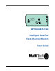
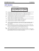
FID1 FID4 TH1 TH3 A1 S6 LED1 LED2 C91 5 1 U11 LED5 2 3 4 LED4 6 S1 7 8 30 367 U8 U22 21 LED3 1 5 14 14 T1 T5 T3 P7 9 10 11 12 P1 JP7 73 37 S2 13 14 15 16 LED7 40 U2 U15 29 LED6 18 7 109 A20 C15 R2 LED8 LED9 FID2 FID3 LED10 TH2 MT5600BR-V92 Intelligent Data/Fax Rack Mounted Modem User Guide
MultiModem®II User Guide MT5600BR-V.92 P/N S000392A Revision A All rights reserved. This publication may not be reproduced, in whole or in part, without prior expressed written permission from Multi-Tech Systems, Inc. Copyright © 2006 by Multi-Tech Systems, Inc. Multi-Tech Systems, Inc. makes no representations or warranties with respect to the contents hereof and specifically disclaims any implied warranties of merchantability or fitness for any particular purpose. Furthermore, Multi-Tech Systems, Inc.
MT5600BR-V92 User Guide Contents Contents Chapter 1 - Introduction .......................................................................................................... 5 Product Description ........................................................................................................................... 5 General features ............................................................................................................................... 5 LED Indicators ..........................
MT5600BR-V92 User Guide Contents Appendix B - Updating Your Modem’s Firmware ............................................................... 23 Introduction ..................................................................................................................................... 23 Upgrade Overview .......................................................................................................................... 23 Appendix C - ASCII Conversion Chart ....................................
MT5600BR-V92 User Guide 1 Introduction Chapter 1 - Introduction Congratulations on your purchase of the MultiModem® II intelligent data/fax modem, model MT5600BR-V92. You have acquired one of the finest internal data/fax modems available today from one of the world’s oldest modem manufacturers: Multi-Tech Systems, Inc. This User Guide will help you to install, configure, test, and use your modem. Product Description The MT5600BR-V92 incorporates ITU-T V.
MT5600BR-V92 User Guide 1 Introduction LED Indicators The MT5600BR-V92 has ten LED diagnostic indicators. RCV XMT CO 56 33.6 14.4 OH DTR RI ERR RCV - This LED blinks when data is being received, on for a space, off for a mark. The state of this RCV LED matches that of the RCV circuit on Pin 3 of the RS232C/V.24 interface. XMT - This LED blinks when data is being transmitted, on for a space, off for a mark. The state of this LED matches that of the XMT circuit on Pin 2 of the RS232C/V.
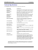
MT5600BR-V92 User Guide 1 Introduction Technical Specifications Your MT5600BR-V92 data/fax modem meets the specifications listed below: Model Number MT5600BR-V92 Server-to-Client Data Rates V.90 speeds when accessing a V.90 or V.92 server (actual speed depends on server capabilities and line conditions)* Client-to-Server Data Rates Up to 50Kbps when accessing a V.92 server (actual speed depends on server capabilities and line conditions); other wise, the same as client-to-client data lines.
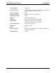
MT5600BR-V92 User Guide 1 Introduction Command Buffer 60 Characters Transmission Level -11 dBm (dial-up), -15dBm (lease line); dBm level selectable with DIP-Switch #3 in lease line setting Frequency Stability ±0.01% Receiver Sensitivity -43 dBm under worst-case conditions AGC Dynamic Range 43 dB Interface EIA RS232C/ITU-TSS V.
MT5600BR-V92 User Guide 1 Introduction Chapter 2 - Installation Safety Warnings • • • • Use this product only with UL- and CUL-listed computers (U.S.A.) To reduce the risk of fire, use only UL-listed 26 AWG (.41mm) or larger telephone wiring. Never install telephone wiring during a lightning storm. Never install a telephone jack in a wet location unless the jack is specifically designed for wet locations.
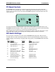
MT5600BR-V92 User Guide 1 Introduction PC Board Controls The MT5600BR-V92 is designed on a single printed circuit board. This board contains sixteen DIPSwitches. There is a two-position"Out of Service" (OOS) toggle switch that extends from the front of the modem circuit card. There is also a two-position TEST/OOS berg jumper located towards the back and center of the card.
MT5600BR-V92 User Guide 2 Installation Switch Function #5 Answer/Originate* (Async/Sync/Leased Line) Position UP* DOWN Effect Answer Mode Originate Mode #6 Max-Throughput Enabled* (Async/Dial-Up/Leased) UP* DOWN Modem set-up to operate at highest efficiency level #6 Slave Clock Disabled* (Sync/Dial-Up/Leased) UP* DOWN Slave Clocking OFF Slave Clocking ON #7 RTS/Normal/Forced* (Sync/Async/Dial/Leased) UP DOWN* RTS dependent on interface RTS forced ON #8 Command Mode Enabled* (Sync/AsyncDial
MT5600BR-V92 User Guide 2 Installation OOS (Busy Out) Toggle Switch The MT5600BR-V92 contains a two-position OOS switch on the front panel. This switch can be used to create a “busy out” (OOS) condition for the modem (i.e., take the modem off-hook). To place a modem in the Busy condition, move the OOS toggle switch to the (BUSY) position. The modem then goes off-hook, its OOS and OH LEDs light, and incoming calls to this modem get a busy signal.
MT5600BR-V92 User Guide 2 Installation Installation Perform the following procedure to install modem cards into the CC1600 rack. The installation process involves: 1. Verify that the DIP-Switch settings conform to your application (dial-up or lease line). 2. Slide a modem card into one of sixteen available modem slots. Start by inserting a modem into the left-most channel (slot #1) of the rack. The toggle switch should be at the bottom of the card, with the component side of the card facing the right.
MT5600BR-V92 User Guide 3 Configuration Chapter 3 - Configuration Configuring Your Software Communications software must be configured to work with your modem, your computer, and the remote system it is calling. Fortunately, most communications programs make the process easy by providing a default initialization string for your modem as well as defaults for most of the other required parameters.
MT5600BR-V92 User Guide 3 Configuration Changing Default Parameters The default values for the other parameters in modem configuration menus rarely need changing. They typically include the dialing prefix (ATDT for touch-tone service and ATDP for rotary service), the dialing suffix (^M), the hang-up string (+++) ”Response” then (ATH0^M), and response messages (RING, NO CARRIER, BUSY, etc.). Communications software with a host mode might also include an auto-answer string (AT S0=1^M).
MT5600BR-V92User Guide 4 AT Commands and Fax Commands Chapter 4 - AT Commands A complete AT Commands, S-Registers, and Result Codes Reference Guide can be found on the MT5600BR-V92 CD and on the Multi-Tech Web site. Fax Commands Fax commands resemble AT commands, but are more complicated to use. Because of this, we recommend that you use a fax program to send and receive faxes rather than attempting to control the modem directly.
MT5600BR-V92 User Guide 5 - Warranty and Repairs Chapter 5 - Warranty and Repairs Multi-Tech Warranty Statement Multi-Tech Systems, Inc., (hereafter “MTS”) warrants that its products will be free from defects in material or workmanship for a period of two, five, or ten years (depending on model) from date of purchase, or if proof of purchase is not provided, two, five, or ten years (depending on model) from date of shipment.
MT5600BR-V92 User Guide 5 - Warranty and Repairs Repair Procedures for International Customers (Outside U.S.A. and Canada) Your original point of purchase Reseller may offer the quickest and most economical repair option for your Multi-Tech product. You may also contact any Multi-Tech sales office for information about the nearest distributor or other repair service for your Multi-Tech product. The Multi-Tech sales office directory is available at http://www.multitech.
MT5600BR-V92 User Guide Appendix A - Regulatory Compliance Appendix A - Regulatory Compliance FCC Part 68 Telecom 1. This equipment complies with part 68 of the Federal Communications Commission Rules. On the outside surface of this equipment is a label that contains, among other information, the FCC registration number. This information must be provided to the telephone company. 2. The suitable USOC jack (Universal Service Order Code connecting arrangement) for this equipment is shown below.
MT5600BR-V92 User Guide Appendix A - Regulatory Compliance FCC Part 15 This equipment has been tested and found to comply with the limits for a Class B digital device, pursuant to Part 15 of the FCC Rules. These limits are designed to provide reasonable protection against harmful interference in a residential installation.
MT5600BR-V92 User Guide Appendix A - Regulatory Compliance Before installing this equipment, users should ensure that it is permissible to be connected to the facilities of the local telecommunications company. The equipment must also be installed using an acceptable method of connection. The customer should be aware that compliance with the above conditions may not prevent degradation of service in some situations.
MT5600BR-V92 User Guide Appendix A - Regulatory Compliance Telepermitted equipment of a different make or model, nor does it imply that any product is compatible with all of Telecom’s network services. This equipment is not capable under all operating conditions of correct operation at the higher speed which it is designated. 33.6 kbps and 56 kbps connections are likely to be restricted to lower bit rates when connected to some PSTN implementations.
MT5600BR-V92User Guide Appendix B - Firmware Upgrade Appendix B - Upgrading the Firmware Introduction Your modem is controlled by semi-permanent software, called firmware, which is stored in flash memory. Firmware is nonvolatile; that is, it remains stored in memory when the modem is turned off. However, it can be changed by either the manufacturer or the user as bugs are fixed or new features are added.
MT5600BR-V92User Guide Appendix B - Firmware Upgrade Step 2 - Identify the Current Firmware Version Identify the current version of the firmware at the Multi-Tech Web site. If your modem already has the current firmware, there is no need to update it. 1. Using your favorite Web browser, go to http://www.multitech.com/support/MultiModemII/ firmware.asp. 2. Scroll down the table to your modem model number. 3. Look at the firmware version number for your modem. 4.
MT5600BR-V92User Guide Appendix B - Firmware Upgrade Step 5 - Clear Your Stored Paramenters Before you flash your modem, you should record the parameters that are currently stored in it, so you can reprogram it after flashing. After you have recorded them, send the AT&F command to the the modem to clear the stored parameters. 1. Run your favorite terminal program. If you are using Windows 98, Windows NT, Windows 2000, or XP you can use HyperTerminal. 2.
MT5600BR-V92 User Guide Appendix C - ACSII Conversion Chart Appendix C - ASCII Conversion Chart CTRL CODE HEX DEC @ NUL 00 0 A SOH 01 1 B STX 02 2 C ETX 03 3 D EOT 04 4 E ENQ 05 5 F ACK 06 6 G BEL 07 7 H BS 08 8 I HT 09 9 J LF 0A 10 K VT 0B 11 L FF 0C 12 M CR 0D 13 N SO 0E 14 O SI 0F 15 P DLE 10 16 Q DC1 11 17 R DC2 12 18 S DC3 13 19 T DC4 14 20 U NAK 15 21 V SYN 16 22 W ETB 17 23 X CAN 18 24 Y EM 19 25 Z SUB 1A 26 [ ESC 1B 27 \ FS 1C 28 ] GS 1D 29 ^ RS 1E 30 _ US 1F 31 NUL SOH STX ETX EOT ENQ ACK BEL BS
MT5600BR-V92 User Guide Appendix D - WEEE Statement Appendix D – Waste Electrical and Electronic Equipment (WEEE) The WEEE directive places an obligation on manufacturers, distributors and retailers to take-back electronics products at the end of their useful life. A sister Directive, ROHS (Restriction of Hazardous Substances), complements the WEEE Directive by banning the presence of specific hazardous substances in the products at the design phase.
Index 33.6K bps ......................................................... 5 ITU-T ................................................................ ITU-T “Super” Group 3 ...................................... ITU-T V.21 ........................................................ ITU-T V.34 fax ................................................... ITU-T V.42 ........................................................ ITU-T V.44 ........................................................ ITU-T V.80 ....................
Index V.32 .................................................................. V.34 .................................................................. V.34 enhanced .................................................. V.34bis .............................................................. V.42 .................................................................. V.42bis .............................................................. V.44 .................................................................. V.90 ......