
User Guide Network Device MT5600BAV.92, MT5600BAV.90, MT5600BLV.90
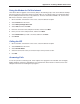
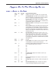
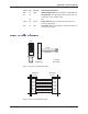
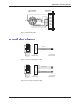
Table Of Contents
- Table of Contents
- Chapter 1 - Description and Features
- Chapter 2 - Installation
- Chapter 3 - Using the Front Panel
- Modem Configuration
- LED Indicators
- Liquid Crystal Display (LCD)
- Option Selection
- Menu Structure
- Menu Overview
- Status Trunk
- Basic Options Trunk
- Advanced Options Trunk
- Remote Configuration Options Trunk
- Diagnostic Options Trunk
- Phone Number Memory Options Trunk
- Caller ID Options Trunk
- Menu Options
- Status
- Basic Options
- Advanced Options
- Remote Configuration Options
- Diagnostic Options
- Phone Number Memory Options
- Caller ID Options
- Chapter 4 - Leased Line Operation
- Chapter 5 - Remote Configuration
- Chapter 6 - Callback Security
- Chapter 7 - Troubleshooting
- None of the Indicators Light
- The Modem Does Not Respond to Commands
- The Modem Cannot Connect When Dialing
- The Modem Disconnects While Online
- The Modem Cannot Connect When Answering
- File Transfer Is Slower Than It Should Be
- Data Is Being Lost
- There Are Garbage Characters on the Monitor
- The Modem Doesn't Work with Caller ID
- Fax and Data Software Can't Run at the Same Time
- Appendix A - Regulatory Compliance
- Appendix B - Technical Specifications
- Appendix C - Warranty, Service, and Technical Support
- Appendix D - Upgrading the Firmware
- Appendix E - Installing a Modem Under Linux
- Appendix F - Pin Descriptions
- Index
Appendix F - Pin Descriptions
63
Multi-Tech Systems, Inc. MT5600BA/BL Series User Guide
RDL 21 RDL Remote Digital Loop Input to modem to enable RDL test.
RI 22 Ring Indicator RI output high indicates the presence of
a ring signal on the telephone line.
23 NC
XCLK 24 XCLK External Clock Input to modem used in special syn-
chronous applications.
TM 25 TM Test Mode Output from modem to indicate modem is in
one of the test modes.
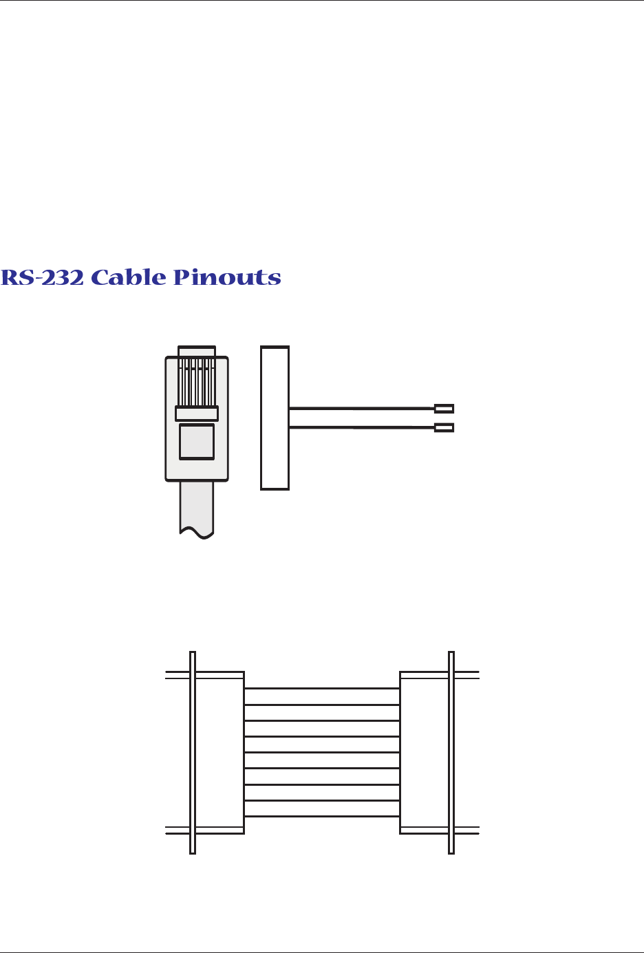
RJ-11
Modular Plug
To Terminal
Block Screws
2345
2
3
4
5
Red (Tip)
Green (Ring)
Fig. F-1. 25-pin to 25-pin RS-232 cable.
20 DTR
22 RI
8CD
7 GND
6 DSR
5 CTS
4 RTS
3RD
2TD
DCE DB-25
connector
DTE DB-9
connector
DTR 4
RI 9
CD 1
GND 5
DSR 6
CTS 8
RTS 7
RD 2
TD 3
Fig. F-2. 9-pin to 25-pin RS-232 cable.
Label Pin I/O type Signal name/description