MT5600BA/BL Series MT5600BA–V.92 MT5600BA–V.90 MT5600BL–V.
MultiModemII User Guide MT5600BA–V.92, MT5600BA–V.90, MT5600BL–V.90 P/N S000276C Revision C ©2003 by Multi-Tech Systems, Inc. All rights reserved. This publication may not be reproduced, in whole or in part, without prior expressed written permission from Multi-Tech Systems, Inc. Multi-Tech Systems, Inc. makes no representations or warranties with respect to the contents hereof and specifically disclaims any implied warranties of merchantability or fitness for any particular purpose.
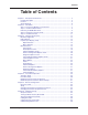
Contents Table of Contents Chapter 1 - Description and Features ......................................................................... 5 Product Description .............................................................................................. 5 Features ............................................................................................................... 5 Safety Warnings ..................................................................................................
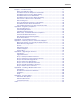
Contents Chapter 7 - Troubleshooting ..................................................................................... None of the Indicators Light ............................................................................... The Modem Does Not Respond to Commands .................................................. The Modem Cannot Connect When Dialing ....................................................... The Modem Disconnects While Online ............................................................
Chapter 1 - Description and Features Chapter 1 - Description and Features Congratulations on your purchase of the MultiModemII modem. You have acquired one of the finest intelligent data/fax modems available today from one of the world’s oldest modem manufacturers: MultiTech Systems, Inc. This user guide will help you install, configure, test and use your modem. Product Description This modem supports two-wire and/or four-wire leased lines.
Chapter 1 - Description and Features Safety Warnings • • • • • • • • Use this product only with UL- and CUL-listed computers. To reduce the risk of fire, use only 26 AWG or larger telephone wiring. Never install telephone wiring during a lightning storm. Never install a telephone jack in a wet location unless the jack is specifically designed for wet locations. Never touch uninsulated telephone wires or terminals unless the telephone line has been disconnected at the network interface.
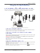
Chapter 2 - Installation Chapter 2 - Installation Step 1 - Connect the Modem to Your System Turn off your computer. Placing the modem in a convenient location, connect it to your computer’s serial port, to the telephone line, to your leased line, to AC power, and, optionally, to your telephone. PHONE LINE LEASED EIA RS232C VOLUME POWER or MultiModemII connections with V.92 transformer and V.90 transformer.
Chapter 2 - Installation Connect the Four-Wire Leased Line MT5600BL Only – Plug one end of a four-wire phone cable into the modem's LEASED jack; connect the other end to a four-wire leased line wall jack or terminals. Modems with a leased-line jack support the dial backup feature. For dial backup operation, plug one end of your dialup modular phone cable into the modem’s LINE jack and the other end into a PSTN wall jack.
Chapter 2 - Installation Step 2 - Install the Modem Driver If you use Windows 98/Me/NT 4.0/2000/XP; you must install the modem driver. The drivers are installed easily since Windows supports Plug-and-Play. Installing the Modem Driver for Windows 98/Me/2000/ XP 1. Make sure your modem is connected properly, and then turn on your computer. Windows should detect your new modem and open the Install New Modem wizard.
Chapter 2 - Installation Step 3 - Setting Your Country Code (MT5600BAV.92 Only) The MT5600BA-V.92 modem is a global modem - it can be used all over the world. Different countries have different requirements for how modems must function. Therefore, before you can use your modem, you must configure it to match the defaults of the country in which you are using it.
Chapter 2 - Installation Using the Global Wizard The Global Wizard configuration utility is recommended for computers running in Windows. The Wizard can configure your modem for a specific country with just a few mouse clicks. 1. Insert the MultiModemII system CD into the CD-ROM drive. The Autorun dialog box appears. 2. Click Initial Setup and Country Selection. The Global Wizard dialog box appears. Click Next. 3. The Global Wizard searches for your modem and identifies it.
Chapter 3 - Using the Front Panel Chapter 3 - Using the Front Panel Like any modem, your Multi-Tech modem operates only under the control of a communication program, such as the PhoneTools program included with the modem. It also operates under other general-purpose data communication programs, such as Windows Terminal and HyperTerminal. For information on how to use the modem with the communication program of your choice, please refer to the program’s documentation.
Chapter 3 - Using the Front Panel Liquid Crystal Display (LCD) The MultiModemII’s backlit liquid crystal display (LCD) has two functions: to display the current status of the modem and to display configuration menus, which are selected using the four pushbuttons on the front panel. Option Selection To select most configuration options, simply display the option in the LCD, and then press the Enter button to select it. An OPTION SET message appears to confirm the selection.
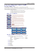
Chapter 3 - Using the Front Panel Menu Overview Trunks Status = , Limbs Branches Status = Idle Twigs Manual Orig.? , , , Ent Manual Answer? , , Ent ( automatic selection ) Status = Online Basic Options , , Remote Config. Diagnostics , , , , Phone Number Memory , Caller I.D.
Chapter 3 - Using the Front Panel Status Trunk The Status Trunk shows the current operating status of the modem. Limb changes are automatic, but certain options can be accessed by pressing the à button. Note that when the modem is online, pressing the à button shows the connect status, including the data speed, connection type, and compression type. Limbs Twigs Manual selection Automatic selection Multi-Tech Systems, Inc.
Chapter 3 - Using the Front Panel Basic Options Trunk Use the Basic Options Trunk to configure the modem’s basic operating conditions. When entering a number, use the áß and â buttons to scroll through a list of digits and characters. To go to the next position, press the à button. To back up or to exit without dialing, press the à button several times. Limbs Branches Twigs Continued on next page Multi-Tech Systems, Inc.
Chapter 3 - Using the Front Panel Basic Options Trunk, continued Limbs Branches Twigs Continued from previous page Multi-Tech Systems, Inc.
Chapter 3 - Using the Front Panel Advanced Options Trunk Use the Advanced Options Trunk to configure RS-232, dial backup, and callback security options. When entering a number or password, use the áß and â buttons to select a character or digit. To go to the next position, press the à button. To backspace or to exit, press the à button several times. Limbs Branches Twigs Continued on next page Multi-Tech Systems, Inc.
Chapter 3 - Using the Front Panel Advanced Options Trunk, continued Limbs Branches Twigs Continued from previous page Multi-Tech Systems, Inc.
Chapter 3 - Using the Front Panel Remote Configuration Options Trunk Use the Remote Configuration Options Trunk to enable or disable remote configuration on the modem, and to change the password. When entering the password, use the áß and â buttons to scroll through the alphabet. To go to the next character position, press the à button. To backspace or to exit, press the à button several times.
Chapter 3 - Using the Front Panel Phone Number Memory Options Trunk The MultiModemII can store up to four telephone numbers for speed dialing. Use the Phone Number Memory Options Trunk to store, list, and dial these numbers. When entering a number, use the áß and â buttons to scroll through the available digits and dialing commands. To go to the next position, press the à button. To backspace or to exit, press the à button several times.
Chapter 3 - Using the Front Panel Menu Options This section describes important LCD screens and options. Many, but by no means all, of the options have AT command equivalents. Status Status screens display the current status of the modem. Though limb changes are automatic, certain options can be selected by pressing the à button. STATUS = IDLE. The modem is ready but inactive. This screen appears when the modem is first turned on, and is the starting point for accessing all other screens.
Chapter 3 - Using the Front Panel Basic Options The following screens are used to configure the modem’s basic operating conditions. ONLINE OPTIONS. The following screens are used to configure the online operation of the modem: LINE TYPE OPTIONS. Use the à and Enter buttons to select from the following line types: dial-up (PSTN), two-wire leased line originate or answer, and four-wire leased line originate or answer. ERROR CORRECTION OPTIONS.
Chapter 3 - Using the Front Panel COMMAND MODE OPTIONS. The following screens are used to configure result code responses. ENABLE/DISABLE RESPONSE. Use the à and Enter buttons to enable or disable the sending of result codes to the computer. Same as the Q0 and Q1 commands. VERBOSE/TERSE RESPONSE. Use the à and Enter buttons to select verbose or terse result codes. Same as the V0 and V1 commands. ENABLE/DISABLE CMD MODE.
Chapter 3 - Using the Front Panel Advanced Options RS232 OPTIONS. The following screens are used to configure the RS-232 interface. DTR OPTIONS. Use the à and Enter buttons to select how the modem responds to the high to low transition of the DTR signal sent by the computer. DTR NORMAL causes the modem to hang up; IGNORE DTR allows operation with computers that do not provide DTR; and RESET ON DTR â causes the modem to perform a soft reset as if the Z command were received.
Chapter 3 - Using the Front Panel CALLBACK SECURITY. Use the à and Enter buttons to turn callback security on or off. Same as the #DB0 and #DB1 commands. For more information about callback security, see Chapter 6, “Callback Security.” PASSWORD SETUP. Use to enter callback security passwords in memory locations 1–30. Each password must be six to ten characters in length. To scroll through a list of digits and characters, press the áß and â buttons. To go to the next position, press the à button.
Chapter 3 - Using the Front Panel Remote Configuration Options The following screens are used to configure remote configuration options. For more information about remote configuration, see Chapter 5, “Remote Configuration.” ENABLE/DISABLE R.C. Use the à and Enter buttons to turn remoteconfiguration on or off. REMOTE CONFIG. PASSWORD. Use to enter the remote configuration password. To scroll through a list of digits and characters, press the áß and â buttons. To go to the next position, press the à button.
Chapter 3 - Using the Front Panel Caller ID Options Press the à and Enter buttons to enable formatted (FCID) or unformatted (UCID) Caller ID, or to disable Caller ID altogether. Same as the #CID=0, #CID=1, and #CID=2 commands. Note: Because Caller ID information is sent between the first and second ring, register S0 must be set to 2 or more rings for the modem to receive Caller ID information. Multi-Tech Systems, Inc.
Chapter 4 - Leased Line Operation Chapter 4 - Leased Line Operation This chapter describes how to use the MultiModemII modem on a leased line. A leased line is a private, permanent, telephone connection between two points. Unlike normal dialup connections, a leased line is always active. The modems automatically connect when they are attached to the line and are turned on.
Chapter 4 - Leased Line Operation Four-Wire Setup 1. For four-wire leased line operation, connect one of the provided four-wire cables to the LEASED jack on the back of the modem. Connect the other end of the cable to a four-wire leased line jack or terminals supplied by the telephone company. 2. Turn on the modem. 3. Starting at the STATUS screen, press the following buttons on the front panel: â, à, â, â, â, à, à, à, à. The SYNC, NORM? screen appears. 4.
Chapter 4 - Leased Line Operation Dial Backup and Leased-Line Restoral For four-wire leased line operation, the MT5600BA-V.92 modem has a dial backup capability, in which the modem is connected to a standard dial-up line as well as to the leased line. If the leased line fails, the originate modem automatically dials and connects to the answer modem through the standard telephone network. While it is in dial backup mode, the modem periodically checks the leased line to see if it is operational.
Chapter 4 - Leased Line Operation 8. To change the default restore time, press â to go to the TIME TO RESTORE (S15) screen, then press à, à. The ENTER TIME IN MINUTES screen appears. 9. Press the áß or â button several times to select the first digit in the number. 10. Press the à button to go to the next digit in the number. 11. Repeat steps 9 and 10 until you have entered a value between 10 and 255, or 0 to disable dial backup, and then press the Enter button to store it. The TIME STORED screen appears.
Chapter 5 - Remote Configuration Chapter 5 - Remote Configuration Remote configuration is a network management tool that allows you to configure modems anywhere in your network from one location. With password-protected remote configuration, you can issue AT commands to a remote MultiModemII modem for maintenance or troubleshooting as if you were on-site. Basic Procedure The following steps are valid regardless of whether the connection is established by the local or the remote MultiModemII modem. 1.
Chapter 5 - Remote Configuration 3. To change the password, press áß or â to select the first character of the password, and then press à to go to the next character. Repeat until you have entered the entire password. 4. To cancel the new password, press à until the password is erased. To save the new password, press the Enter button. The next time you remotely configure the modem you must use the new password.
Chapter 6 - Callback Security Chapter 6 - Callback Security This chapter describes how to use callback security with your modem. Callback security protects your network from unauthorized access and helps control long distance costs. When callback security is enabled, all callers are requested to enter a password. If the password is invalid, the caller can try twice more before the modem hangs up.
Chapter 6 - Callback Security Front Panel Method 1. Turn on the modem. 2. Starting at the STATUS screen, press the following buttons on the front panel to turn callback security on and off: · To turn on callback security, press â, â, à, â, â, à, à to display the CALLBACK ON? option, and then press the Enter button to select the option. When remote callback security is turned on, each caller is asked to enter a password, then is disconnected and called back by the modem.
Chapter 6 - Callback Security 7. Press the Enter button again to go to the PASSWORD SETUP screen. 8. Press à, à to go to the ENTER PASSWORD #2? screen. 9. Repeat steps 3–7 to enter the next password. 10. Repeat as many times as necessary, up to memory location 30, until all passwords have been entered. Warning: There is no way to review an entry to confirm that it has been entered correctly.
Chapter 6 - Callback Security 8. Press à, à to go to the ENTER NUMBER #2? screen. 9. Repeat steps 3–7 to enter the next number. 10. Repeat as many times as necessary, up to memory location 30, until all numbers have been entered. Warning: There is no way to review an entry to confirm that it has been entered correctly. If you attempt to look at a number entry by pressing the Enter button for an ENTER NUMBER #n? screen, it is possible for you to accidentally erase the entry.
Chapter 6 - Callback Security Callback Security Commands The following AT commands are used with callback security. Command: #DBn Values: Default: Description: #DB0 #DB1 Callback Enable/Disable n = 0 or 1 0 Enables or disables callback security. When callback security is enabled, phone number memory locations 0–4, used for quick dialing and DTR dialing, become unavailable and are replaced by callback security memory locations 1–30.
Chapter 6 - Callback Security Callback Assignments Form Location 01 02 03 04 05 06 07 08 08 10 11 12 13 14 15 16 17 18 19 20 21 22 23 24 25 26 27 28 29 30 Password Multi-Tech Systems, Inc.
Chapter 7 - Troubleshooting Chapter 7 - Troubleshooting Your modem was thoroughly tested at the factory before it was shipped. If you are unable to make a successful connection, or if you experience data loss or garbled characters during your connection, it is possible that the modem is defective. However, it is more likely that the source of your problem lies elsewhere. The following symptoms are typical of problems you might encounter: · None of the LEDs light when the modem is on.
Chapter 7 - Troubleshooting The Modem Does Not Respond to Commands · Make sure the modem is plugged in and turned on. (See “None of the Indicators Light.”) · Make sure you are issuing the modem commands from data communication software, either manually in terminal mode or automatically by configuring the software. (You cannot send commands to the modem from the DOS prompt.) · Make sure you are in terminal mode in your data communication program, then type AT and press ENTER.
Chapter 7 - Troubleshooting Windows 9x: Right-click on My Computer, select Properties from the menu, click on the Device Manager tab, double-click on Ports, then double-click on the communication port your modem is connected to. In the port’s Properties sheet, click on the Resources tab to see the port’s input/ output range and interrupt request. If another device is using the same address range or IRQ, it appears in the Conflicting Device List.
Chapter 7 - Troubleshooting · If the modem reports BUSY, the other number might be busy, in which case you should try again later, or it might indicate that you have failed to add a 9, prefix to the phone number if you must dial 9 for an outside line. If you must dial 9 to get an outside line, the easiest way to dial it automatically is to include it in the modem’s dial prefix, e.g., ATDT9,. Note the comma, which inserts a pause before the number is dialed.
Chapter 7 - Troubleshooting The Modem Cannot Connect When Answering · The default DTR Control command (&D2) inhibits autoanswer. To enable autoanswer, change DTR Control to &D0, and make sure &Q0, &Q1, &Q5, or &Q6 is also set. For more information, see the &D command in the AT Command Reference Guide on the CD shipped with your modem. For information on changing the modem’s default configuration, see “Step 3: Install and Configure Your Software” in Chapter 2. · Autoanswer might be disabled.
Chapter 7 - Troubleshooting · Try entering the &V1 command to display information about the last connection, making a screen print of the connection statistics, and checking for parameters that might be unacceptable. There Are Garbage Characters on the Monitor · Your computer and the remote computer might be set to different word lengths, stop bits, or parities. If you have connected at 8-N-1, try changing to 7-E-1, or vice-versa, using your communication software.
Appendix A - Regulatory Compliance Appendix A - Regulatory Compliance FCC Part 68 Telecom 1. This equipment complies with part 68 of the Federal Communications Commission Rules. On the outside surface of this equipment is a label that contains, among other information, the FCC registration number. This information must be provided to the telephone company. 2. The suitable USOC jack (Universal Service Order Code connecting arrangement) for this equipment is shown below.
Appendix A - Regulatory Compliance Fax Branding Statement The Telephone Consumer Protection Act of 1991 makes it unlawful for any person to use a computer or other electronic device, including fax machines, to send any message unless such message clearly contains the following information: · Date and time the message is sent · Identification of the business or other entity, or other individual sending the message · Telephone number of the sending machine or such business, other entity, or individual
Appendix A - Regulatory Compliance EMC, Safety, and R&TTE Directive Compliance The CE mark is affixed to this product to confirm compliance with the following European Community Directives: · Council Directive 89/336/EEC of 3 May 1989 on the approximation of the laws of Member States relating to electromagnetic compatibility; and · Council Directive 73/23/EEC of 19 February 1973 on the harmonization of the laws of Member States relating to electrical equipment designed for use within certain voltage limits
Appendix A - Regulatory Compliance 4. This device is equipped with pulse dialing, while the Telecom standard is DTMF tone dialing. There is no guarantee that Telecom lines will always continue to support pulse dialing. Use of pulse dialing, when this equipment is connected to the same line as other equipment, may give rise to ‘bell tinkle’ or noise and may also cause a false answer condition. Should such problems occur, the user should not contact the Telecom Faults Service.
Appendix B - Technical Specifications Appendix B - Technical Specifications Your MultiModemII modem meets the following specifications: Trade Name MultiModemII™ Model Number MT5600BA-V.92, MT5600-V.90, MT5600BL Server-to-Client Data Rates 56K or V.92 speeds when accessing a 56K or V.
Appendix B - Technical Specifications Frequency Stability ±0.01% Receiver Sensitivity -43 dBm under worst-case conditions AGC Dynamic Range 43 dB Interface TIA/EIA RS-232C/ITU-T V.24/V.
Appendix C - Warranty, Service, and Technical Support Appendix C - Warranty, Service, and Technical Support Multi-Tech Systems, Inc. Warranty & Repairs Policies Warranty Multi-Tech Systems, Inc., (hereafter “MTS”) warrants that its products will be free from defects in material or workmanship for a period of two, five, or ten years (depending on model) from date of purchase, or if proof of purchase is not provided, two, five, or ten years (depending on model) from date of shipment.
Appendix C - Warranty, Service, and Technical Support Repair Procedures for International Customers (Outside U.S.A. and Canada) Your original point of purchase Reseller may offer the quickest and most economical repair option for your Multi-Tech product. You may also contact any Multi-Tech sales office for information about the nearest distributor or other repair service for your Multi-Tech product. http://www.multitech.com/COMPANY/offices/DEFAULT.
Appendix C - Warranty, Service, and Technical Support A Returned Materials Authorization (RMA) is not required. Return shipping charges (surface) will be paid by MTS. Please include inside the shipping box a description of the problem, a return shipping address (must have street address, not P.O. Box), a telephone number, and if the product is out of warranty, a check or purchase order for repair charges. For out of warranty repair charges, go to http://www.multitech.com/documents/warranties.
Technical Support Appendix C - Warranty, Service, and Technical Support Multi-Tech Systems has an excellent staff of technical support personnel available to help you get the most out of your Multi-Tech product. If you have any questions about the operation of this unit, please call 800 9722439 (USA and Canada) or 763 785-3500 (international and local). Please have modem information available.
Appendix D - Upgrading the Firmware Appendix D - Upgrading the Firmware Introduction Your modem is controlled by semi-permanent software, called firmware, which is stored in flash memory. Firmware is nonvolatile; that is, it remains stored in memory when the modem is turned off. However, it can be changed by either the manufacturer or the user as bugs are fixed or new features are added.
Appendix D - Upgrading the Firmware Step 2 - Identify the Current Firmware Version Identify the current version of the firmware at the Multi-Tech Web site. If your modem already has the current firmware, there is no need to update it. 1. Using your favorite Web browser, go to http://www.multitech.com/support/MultiModemII/ firmware.asp. 2. Scroll down the table to your modem model number. 3. Look at the firmware version number for your modem. 4.
Appendix D - Upgrading the Firmware Step 5 - Clear Your Stored Paramenters Before you flash your modem, you should record the parameters that are currently stored in it, so you can reprogram it after flashing. After you have recorded them, send the AT&F command to the the modem to clear the stored parameters. 1. Run your favorite terminal program. If you are using Windows 95, Windows 98, Windows NT, or Windows 2000, you can use HyperTerminal. 2.
Appendix E - Installing a Modem Under Linux Appendix E - Installing a Modem Under Linux Introduction This appendix explains how to install a modem on a computer operating under the Red Hat Linux 6.2 operating system. Other versions of Red Hat and other Linux operating systems should be similar. Briefly, in Linux, you do not need drivers for most standard external modems and most internal ISA bus modems. Programs in Linux commonly call upon the port, rather than the modem.
Appendix E - Installing a Modem Under Linux Using the Modem to Call the Internet Linux allows different graphic user interfaces (GUI). In the following steps, we’ll use the Gnome Desktop GUI and assume that the Internet Service Provider (ISP) you are calling assigns you the Domain Name Service (DNS) and Internet Protocol (IP) addresses. For more information on DNS or IP, see the Linux OS owner’s manual or contact your ISP. 1. On the Task Bar at the bottom of the screen, select the Gnome Footprint. 2.
Appendix F - Pin Descriptions Appendix F - Pin Descriptions RS-232 Pin Descriptions Label Pin CGND 1 TD 2 Transmitted Data The DTE uses the TD line to send data to the modem for transmission over the telephone line or to transmit commands to the modem. RD 3 Received Data The modem uses the RD line to send data received from the telephone line to the DTE and to send modem responses to the DTE. RTS 4 Request to Send The RTS signal is used for hardware flow control.
Appendix F - Pin Descriptions Label Pin I/O type Signal name/description RDL 21 RDL Remote Digital Loop Input to modem to enable RDL test. RI 22 Ring Indicator RI output high indicates the presence of a ring signal on the telephone line. 23 NC XCLK 24 XCLK External Clock Input to modem used in special synchronous applications. TM 25 TM Test Mode Output from modem to indicate modem is in one of the test modes.
Appendix F - Pin Descriptions DCE DB-25 connector DTE Mini-DIN 8-pin connector TxD- 2 3 4 5 6 7 8 20 22 SG, RxD+ RxD- 6 7 8 3 4 5 1 2 HSKi (CTS) HSKo (RTS) TD RD RTS CTS DSR GND CD DTR RI Fig. F-3. Macintosh cable. Leased Line Pinouts 2345 2 3 4 5 Red (Tip) Green (Ring) RJ-11 Modular Plug To Terminal Block Screws Fig. F-4. Two-wire leased line cable. 2345 3 4 2 5 Red Transmit Pair Green Yellow Receive Pair Black RJ-11 Modular Plug To Terminal Block Screws Fig. G-5.
Index Index A advanced menu options 25 Advanced Options Trunk 18 analog loopback test 27 AT commands 5 #CBN= 26, 39 #CBP= 26, 27, 39 #CID= 28 #DB 26, 27, 39 %Q 26 &C 25 &D 25, 45 &Q 45 &R 24, 25 &W 34 &Z= 27 DS= 27 O 34 S= 26 S? 26 autoanswer 45 connecting the modem 7 Country Codes List 10 CTS (Clear to Send) menu options 18, 24, 25 D data compression 45 Diagnostic Options Trunk 20 diagnostics line signal quality 26 menu options 20, 27 dial backup 25, 31–32 dial-back timer 18, 25, 31 dialing menu options
Index serial cable 42 serial port 42, 43, 45 servicing your modem 47 Set Country Code Using AT Commands 11 Set Country Code Using Global Wizard 11 Set Country Code Using LCDs 10 solving problems 41–46 specifications, technical 51–52 Status Trunk 15 Store Callback Number command 39 Store Callback Password command 39 Sync/Async Mode command 45 sync/async modes 16, 24 Windows 3.