
User manual


Appendix B – Product Approvals, Regulatory Design Considerations, Compliance
Multi-Tech Systems, Inc. MT2456SMI-22 SocketModem Developer’s Guide 51
SocketModem Placement
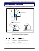
This figure illustrates where to place the SocketModem on a typical application. It must be placed so that the
analog end is near the phone jack.
Analog to Digital Barrier
(Shown for Reference Only)
A
D (Power and GND)
D (Analog)
B or C
Note: The locking end of C should
go in the Motherboard.
E (Digital)
G
Note: The modem should be placed with the
analog pins as close as possbile to the line jack.
F
0.035 [0.889] Drill with 0.060 [1.524] Pad
0.125 [3.175] Non-Plated
1.732
[44]
.750
[19.05]
.0787 TYP
[2]
.945
[24.003]
.145
[3.683]
Figure B–3. SocketModem Placement
Note: The dimensions in this diagram are examples only.
See the mechanical drawing in Chapter 2 for true dimensions.
Key
Qty Ref Name Description
1 A Reference Generic Motherboard
1 B (or C) Recommended RICHCO DLMSPM-4-01 Support Post (L=.250”)
1 C (or B) Recommended RICHCO MSPM-4-01 Support Post (L=.250”)
2 D Recommended Singatron Enterprises 1211-04-S-01-B)
2 E Recommended Singatron Enterprises 1211-10-S-01-B)
1 F Reference ModemModule Assembly
1 G Reference Line Jack
Note: The analog to digital barrier is really a safety isolation barrier between TNV and SELV.