SocketModemÔ Embedded Modem MT2456SMI–22 Serial Interface Developer’s Guide
Copyright SocketModemÔ MT2456SMI–22 Developer’s Guide PN S000281A, Version A Copyright This publication may not be reproduced, in whole or in part, without prior expressed written permission from MultiTech Systems, Inc. All rights reserved. Copyright © 2003, by Multi-Tech Systems, Inc. Multi-Tech Systems, Inc. makes no representations or warranties with respect to the contents hereof and specifically disclaims any implied warranties of merchantability or fitness for any particular purpose.
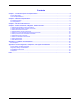
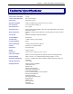
Contents Chapter 1 – Product Description and Specifications .................................................................................................4 Product Description....................................................................................................................................................4 Technical Specifications.............................................................................................................................................
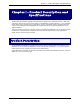
Chapter 1 – Product Description and Specifications Chapter 1 – Product Description and Specifications The Multi-Tech SocketModem supports analog data modem operation with V.22bis Fast Connect, V.42bis data compression, and V.80 synchronous access mode. The SocketModem is a space-efficient (1" × 2.5"), embedded modem that is ready-to-integrate into your applications; therefore, dramatically reducing development time and costs for system designers.
Chapter 1 – Product Description and Specifications Technical Specifications The SocketModem meets the following specifications: Client-to-Server Data Rates V.22 bis Client-to-Client Data Rates 2400, 1200, 0-300 bps Data Format Serial, asynchronous Modem Compatibility V.22bis, V.22; Bell 212A and 103/113; ITU-T V.21 & V.23 Error Correction ITU-T V.42 (LAP-M or MNP 2–4) Data Compression ITU-T V.
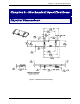
Chapter 2 - Mechanical Specifications Chapter 2 – Mechanical Specifications Physical Dimensions Figure 2–1. Maximum Component Height Multi-Tech Systems, Inc.
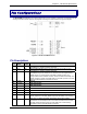
Chapter 2 - Mechanical Specifications Pin Configurations The MT2456SMI SocketModem with a serial interface use a 16-pin interface to provide an on-board DAA with tip and ring connections, audio circuit for call-progress monitoring and serial interface via logic level signals. Figure 2–2. Serial SocketModem Pins Pin Descriptions Pin # 1 Signal Name Tip I/O Type I/O 2 Ring I/O 24 –RESET I 26 DGND Tip Signal from Telco. Tip connection to the phone line (RJ11 Pin 3).
Chapter 2 - Mechanical Specifications 41 DGND Ring Indicate. –RI output ON (low) indicates the presence of an ON segment of a ring signal on the telephone line. The modem will not go off-hook when – RI is active; the modem waits for –RI to go inactive before going off-hook. Data Set Ready. -DSR indicates modem status to the DTE. –DSR OFF (high) indicates that the DTE is to disregard all signals appearing on the interchange circuits except Ring Indicator (–RI).
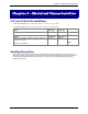
Chapter 3 - Electrical Characteristics Chapter 3 – Electrical Characteristics 3.3V and 5V Serial SocketModem 3.3V DC Characteristics (TA = 0°C to 70°C; VDD = 3.3 V ± 0.3 V) 5V DC Characteristics (TA = 0°C to 50°C; VDD = 5 V ± 0.25 V) Inputs –DTR (40), –TXD (35), –RTS (33), –RESET (24) Outputs –DCD (39), –CTS (38), –DSR (37), –RI (36), –RXD (34) 2mA, Z INT = 120 Ω VDDMAX = VDDMAX = 3.6 V 5.25 V Input High Min 2.0 V Input Low Max 0.8 V Output High Min 2.4 V Output Low Max 0.
Chapter 4 - V.22bis Commands Chapter 4 - V.22bis Commands, SRegisters, and Result Codes The V.
Chapter 4 - V.
Chapter 4 - V.22bis Commands V.22bis Generic Modem Control Commands Z Soft Reset and Restore Profile This command causes the modem to perform a soft reset and restore (recall) the factory default configuration (profile). If no is specified, zero is assumed. Syntax Z Defined Values Decimal number corresponding to the selected profile. 0 Soft reset and restore stored profile. 1 Same as 0; allowed for compatibility.
Chapter 4 - V.22bis Commands 2 Selects reliable (error-correction) mode. The modem will first attempt a LAPM connection and then an MNP connection. Failure to make a reliable connection results in the modem hanging up. (Forces &Q5, S36=4, and S48=7.) 3 Selects auto-reliable mode. This operates the same as \N2 except failure to make a reliable connection results in the modem falling back to the speed buffered normal mode. (Forces &Q5, S36=7, and S48=7.) 4 Selects LAPM error-correction mode.
Chapter 4 - V.22bis Commands &F Restore Factory Configuration (Profile) The modem loads the factory default configuration (profile). The factory defaults are identified for each command and in the S-Parameter descriptions. A configuration (profile) consists of a subset of S-Parameters. Syntax &F[] Defined Values Decimal number corresponding to the selected configuration. 0 Restore factory configuration 0. 1 Same as 0; allowed for compatibility.
Chapter 4 - V.22bis Commands V.22bis DTE/DCE-Modem Interface commands The parameters defined in this section control the operation of the interface between the DTE/DCE and modem. E Command Echo The modem enables or disables the echo of characters to the DTE. The valid parameter value is written to S14 bit 1. Syntax E Defined Values Decimal number corresponding to the option. 0 Disables command echo. 1 Enables command echo.
Chapter 4 - V.22bis Commands X Extended Result Codes This command selects the subset of the result code messages used by the modem to inform the DTE of the results of commands. Blind dialing is enabled or disabled by country parameters. If the user wishes to enforce dial tone detection, a "W" can be placed in the dial string (see D command). The information below is based upon the default implementation of the X results table.
Chapter 4 - V.
Chapter 4 - V.22bis Commands &R RTS/CTS Option This selects how the modem controls CTS. CTS operation is modified if hardware flow control is selected (see &K command). The parameter value, if valid, is written to S21 bit 2. Syntax &R Defined Values Decimal number corresponding to the selected option. 0 In sync mode, CTS tracks the state of RTS; the RTS-to-CTS delay is defined by S26. In async mode, CTS is normally ON and will turn OFF only if required by flow control.
Chapter 4 - V.22bis Commands +IBC In Band Commands This command provides a mechanism by which an in-band secondary channel may be implemented. This in-band secondary channel can be utilized to transparently exchange commands and responses to/from the modem during a data connection. This is an alternative approach to using the +++ escape sequence. The +IBC command also provides a mechanism to exchange V.24 signaling via the secondary channel.
Chapter 4 - V.22bis Commands Table of Supported V.80 Commands Command Hex Codes Description Supported V.80 DTE-to-DCE Commands <40h> The DCE decodes this as a sequence of 3 + (-1Fh). <42h> <105off> <42h> Circuit 105 is OFF. <105on> <43h> Circuit 105 is ON. <58h> The DCE decodes this as one <99h> in user data. <59h> The DCE decodes this as <99h><99h> in user data. <5Ch> The DCE decodes this as on <19h> in user data.
Chapter 4 - V.22bis Commands V.22bis Call Control Commands D Dial This command directs the modem to go on-line, dial according to the string entered and attempt to establish a connection. If no dial string is supplied, the modem will go on-line and attempt the handshake in originate mode. Note: If the ATD command is issued before the S1 register has cleared, the modem will respond with the NO CARRIER result code. The modem will behave as a data modem and will attempt to connect to another data modem.
Chapter 4 - V.22bis Commands T Set Tone Dial Default This command forces DTMF dialing until the next P dial modifier or P command is received. The modem will set an S-Parameter bit to indicate that all subsequent dialing should be conducted in tone mode. The DP command will override this command. Clears S14 bit 5. This command may not be permitted in some countries. (See P.) Result Code OK P Set Pulse Dial Default This command forces pulse dialing until the next T dial modifier or T command is received.
Chapter 4 - V.22bis Commands M Speaker Control This command selects when the speaker will be on or off. The parameter value, if valid, is written to S22 bits 2 and 3. Syntax M Defined Values Decimal number corresponding to the selected option. 0 Speaker is always off. 1 Speaker is on during call establishment, but off when receiving carrier. (Default) 2 Speaker is always on. 3 Speaker is off when receiving carrier and during dialing, but on during answering.
Chapter 4 - V.22bis Commands \V Single Line Connect Message Enable This command enables or disables the single line connect message format as follows: Syntax \V Defined Values Decimal number corresponding to the selected option. 0 Connect messages are controlled by the command settings X, W, and S95. 1 Connect messages are displayed in the single line format described below subject to the command settings V (Verbose) and Q (Quiet).
Chapter 4 - V.22bis Commands *D Display Delayed Numbers This command causes the modem to send a list of the delayed numbers together with the delay associated with each. The modem will return a list of delayed telephone numbers as defined in the *B command. The format of the response is shown by the example below (delay times are shown as hours:minutes:seconds). If no numbers are delayed, only the OK result code is issued. Syntax *D Example NO.
Chapter 4 - V.22bis Commands Extension Pick-up (Enabled by AT-STE=2, AT-STE=3, AT-STE=6, or AT-STE=7): Case 1: Modem off-hook, Local Handset Goes Off-Hook If the local handset goes off-hook while the modem is in a data connection, the local handset will be muted. The modem will then send a GSTN Cleardown to the remote modem and then go on-hook. The modem will then send a NO CARRIER message to the DTE. A result code of 25 will be left in S86 register.
Chapter 4 - V.22bis Commands V.22bis Modulation Control Commands +MS Modulation Selection This extended-format compound parameter controls the manner of operation of the modulation capabilities in the modem. It accepts six subparameters. Syntax +MS=[[,[,[,[,[,]]]]]] Table of +MS Command Supported Rates Modulation Bell 103 Bell 212 V.21 V.22 V.22bis V.
Chapter 4 - V.22bis Commands %E Enable/Disable Line Quality Monitor and Auto-Retrain Controls whether or not the modem will automatically monitor the line quality and request a retrain (%E1). The parameter value, if valid, is written to S41 bits 2 and 6. If enabled, the modem attempts to retrain for a maximum of 30 seconds. Syntax %E Defined Values Decimal number corresponding to the selected option. 0 Disable line quality monitor and auto-retrain.
Chapter 4 - V.22bis Commands V.22bis Error Control and Data Compression Commands +ESR Selective Repeat This extended-format numeric parameter controls the use of the selective repeat (SREJ) option in V.42. Syntax +ESR=[] Decimal number 0 specifying that SREJ is not used.
Chapter 4 - V.22bis Commands \K Break Control Controls the response of the modem to a break received from the DTE or the remote modem or the \B command. The parameter value, if valid, is written to S40 bits 3, 4, and 5. Syntax \K Defined Values Decimal number corresponding to the selected option. The response is different in three separate states.
Chapter 4 - V.22bis Commands V.22bis Synchronous Access Mode Commands Three commands support Synchronous Access Mode: +ES enables and disables Synchronous Access Mode in the client or central site modem. Enabling Synchronous Access Mode enables the use of the 8-bit command characters of the Draft ITU-T Recommendation V.80 (See the table under the +IBC command - Data Communication over the Telephone Network. In-Band DCE Control Command).
Chapter 4 - V.22bis Commands +ITF Transmit Flow Control Thresholds The +ITF command determines the flow control thresholds used by the modem for transmit data from the DTE. This optional compound parameter allows the DTE to determine the input buffer size in the modem for data on circuit 103 (transmit data) from the DTE, to control the thresholds used for flow control of such data, and to control how often the modem reports to the DTE the number of octets in this buffer.
Chapter 4 - V.22bis Commands V.22bis FastConnect Command $F Fast Connect Control This command allows configuring of the client modem to connect to a central site modem that supports non-standard V.22 and V.22bis Fast Connect protocols. Syntax $F Defined Values Decimal number which specifies the initial requested mode of operation when the modem is operating as the originator.
Chapter 4 - V.22bis Commands V.22bis Line Side Device Commands -TTE Threshold Adjustments for Telephony Extension This command allows the host to set/tune the telephone line voltage level drop threshold necessary for the modem to determine Line-in-Use, Extension Pickup, and Remote Hangup conditions. An ATZ or AT&F will load default values.
Chapter 4 - V.22bis Commands V.22bis S-Parameters The S-Parameters are summarized in the S-Parameter Table along with their default values which may be loaded at any time by using the Z command. Registers or register fields quoted as “reserved” are reserved for current or future use by the firmware or are permanently overridden by PTT limitations. For the latter, control of the equivalent functionality is available with Blacklisting options. All bit-mapped registers are read-only.
Chapter 4 - V.
Chapter 4 - V.22bis Commands S-PARAMETER DEFINITIONS S0 - Number of Rings to Auto-Answer S0 sets the number of the rings required before the modem automatically answers a call. Setting this parameter to zero disables auto-answer mode. Range: 0-255 rings Default: 0 S1 - Ring Counter S1 is incremented each time the modem detects a ring signal on the telephone line. S1 is cleared if no rings occur over an eight second interval.
Chapter 4 - V.22bis Commands S8 - Pause Time For Dial Delay S8 sets the time, in seconds, that the modem must pause when the “,” dial modifier is encountered in the dial string. Range: 2-255 seconds Default: 2 S9 - Carrier Detect Response Time S9 is supported for backwards compatibility only. No value can be written. Responds with default value. Range: 6 tenths of a second Default: 6 (0.
Chapter 4 - V.22bis Commands S16 - Test Mode Bit Mapped Options Status S16 indicates the test in progress status. Default: 0 Bit 0 Local analog loopback. 0 = Disabled. (Default) 1 = Enabled.
Chapter 4 - V.22bis Commands S22 - Speaker/Results Bit Mapped Options Status S22 indicates the status of command options. Default: 117 (75h) (01110101b) Bits 0-1 Speaker volume (Ln). 0 = Off (L0). 1 = Low (L1). (Default) 2 = Medium (L2). 3 = High (L3). Bits 2-3 Speaker control (Mn). 0 = Disabled (M0). 1 = Off on carrier (M1). (Default) 2 = Always on (M2). 3 = On during handshake (M3). Bits 4-6 Limit result codes (Xn). 0 = X0. 4 = X1. 5 = X2. 6 = X3. 7 = X4. (Default) Bit 7 Reserved.
Chapter 4 - V.22bis Commands S27 - Bit Mapped Options Status S27 indicates the status of command options. Default: 73 (49h) (01001001b) Bits 0,1,3 Synchronous/asynchronous selection (&Mn/&Qn). 31 0 00 0 = &M0 or &Q0. 00 1 = &M1 or &Q1. 01 0 = &M2 or &Q2. 01 1 = &M3 or &Q3. 10 0 = Reserved. 10 1 = &Q5. (Default) 11 0 = &Q6. Bit 2 Leased line control (&Ln). 0 = Dial up line (&L0). (Default) Bits 4 - 5 Internal clock select (&Xn). 0 = Internal clock (&X0). (Default) 1 = External clock (&X1).
Chapter 4 - V.22bis Commands S36 - LAPM Failure Control Default: 7 (00000111b) Bits 0-2 This value indicates what should happen upon a LAPM failure. These fallback options are initiated immediately upon connection if S48=128. If an invalid number is entered, the number is accepted into the register, but S36 will act as if the default value has been entered. 0 = Modem disconnects. 1 = Modem stays on-line and a Direct mode connection is established. 2 = Reserved.
Chapter 4 - V.22bis Commands S41 - General Bit Mapped Options Status S41 indicates the status of command options. Default: 13 (C3h) (00001101b) Bits 0-1 Compression selection (%Cn). 0 = Disabled (%C0). 1 = MNP 5 (%C1). 2 = V.42 bis (%C2). 3 = MNP 5 and V.42 bis (%C3). (Default) Bits 2 Auto retrain (%En). 0 = Retrain disabled (%E0). 1 = Retrain enabled (%E1). (Default) Bit 3-7 Reserved. S48 - V.42 Negotiation Action The V.42 negotiation process determines the capabilities of the remote modem.
Chapter 4 - V.22bis Commands S91 – PSTN Transmit Attenuation Level S91 sets transmit attenuation level from 0 to 15 dBm for the PSTN mode, resulting in a transmit level from 0 to -15 dBm. Range: 0 to 15 dBm (Corresponding to 0 to -15 dBm transmit level.) Default: 10 (-10 dBm transmit level.) S95 - Extended Result Codes Control A bit set to a 1 in this parameter, in conjunction with the W command, will enable the corresponding extended result code.
Chapter 4 - V.22bis Commands V.22bis Result Codes The modem responds to commands from the DTE and to activity on the line by signaling to the DTE in the form of result codes. . Two forms of each result code are available: long-form, an English-like "verbose" response, and short-form, a datalike numeric response (included in parentheses following the long-form). The long-form code is preceded and terminated by the sequence < CR> < LF>. The short-form is terminated by < CR>, only with no preceding sequence.
Chapter 4 - V.22bis Commands Code 16 Message CONNECT 19200 22 24 CONNECT 75TX/1200RX CONNECT 1200TX/75RX DELAYED 32 BLACKLISTED 59 CONNECT 16800 61 CONNECT 21600 62 CONNECT 24000 63 CONNECT 26400 64 CONNECT 28800 83 LINE IN USE 84 CONNECT 33600 91 CONNECT 31200 23 Meaning The modem has connected to the line, the DTE speed is 19200 bps and DTE speed reporting is enabled. The modem has established a V.23 originate connection and line speed reporting is enabled.
Appendix A – Test/Demo Card Information Appendix A – Test/Demo Card Information Block Diagram Power Switch Power Supply Speaker DS1 Volume Control Modem Module Transceiver (RS-232) Tip/Ring Fuse Power Connector DB-25 RS-232 RJ-11 Connector Figure A–1. Serial Test/Demo Board Block Diagram Multi-Tech Systems, Inc.
Appendix B – Product Approvals, Regulatory Design Considerations, Compliance Appendix B - Product Approvals, Compliance, and Layout Considerations Product Safety and EMC Approvals Safety EMC UL 60950 CSA 950 EN 60950 AS 3260 FCC Part 15 (Class B) Canada (Class B) EN 55022 (Class B) EN 55024 Country Certifications While this device can be configured for specific country operation, doing so DOES NOT constitute country approval. This modem is not approved in or configured for operation in all countries.
Appendix B – Product Approvals, Regulatory Design Considerations, Compliance Regulatory Design Considerations This section discusses hardware considerations, safety, and Telecom labeling requirements. Hardware Considerations Disclaimer: Multi-Tech Systems makes no warranty claims for vendor product recommendations listed below. Other vendor products may or may not operate satisfactorily.
Appendix B – Product Approvals, Regulatory Design Considerations, Compliance Recommended Ferrite (SMT) Manufacturer – Associated Component Technology (ACT) – Part # - YCB-1206 Manufacturer – Murata Erie – Part # - BLM31A601SPT Recommended Ferrite (Thru-Hole) Manufacturer – Associated Component Technology (ACT) – Part # - WB2-2.
Appendix B – Product Approvals, Regulatory Design Considerations, Compliance SocketModem Placement This figure illustrates where to place the SocketModem on a typical application. It must be placed so that the analog end is near the phone jack. 0.035 [0.889] Drill with 0.060 [1.524] Pad .0787 TYP [2] 0.125 [3.175] Non-Plated Analog to Digital Barrier (Shown for Reference Only) 1.732 [44] .750 [19.05] .145 [3.683] .945 [24.003] B or C Note: The locking end of C should go in the Motherboard.
Appendix B – Product Approvals, Regulatory Design Considerations, Compliance Compliance Multi-Tech Systems, Inc. Compliance This section discusses Multi-Tech’s SocketModem compliance with 47 CFR Part 68 and Industry Canada CS-03 Telecom regulations. Telecom Requirements for the United States FCC Part 15 Regulation This equipment has been tested and found to comply with the limits for a Class B digital device, pursuant to Part 15 of the FCC rules.
Appendix B – Product Approvals, Regulatory Design Considerations, Compliance 8. No repairs are to be made by you. Repairs are to be made only by Multi-Tech Systems or its licensees. Unauthorized repairs void registration and warranty. 9. If your home has specially wired alarm equipment connected to the telephone line, ensure the installation of this equipment does not disable your alarm equipment.
Appendix B – Product Approvals, Regulatory Design Considerations, Compliance Labeling Continuity and Changes The labeling content and format requirements in effect when a product was approved shall be effective for the life of the product. The labeling content and format requirements in effect at approval shall also continue to be effective for modified products. However, the responsible party shall have the option of conforming a product's labeling to current content and format requirements at any time.
Appendix B – Product Approvals, Regulatory Design Considerations, Compliance (ii) For a new model that is registered to a family of previously certified TE, the self-marking format shall be: IC: XXXXXX-ZZZZZZZZ Where: · “XXXXXX” is the Company Number, as in (d) above ; and · “ZZZZZZZZ” is either the old certification number minus the old company number, or a new Unique Product Number assigned by the applicant.
Appendix B – Product Approvals, Regulatory Design Considerations, Compliance 7. 8. Some parameters required for compliance with Telecom’s Telepermit requirements are dependent on the equipment (PC) associated with this device.
Index Index $F – FastConnect Control, 33 %L - Report Line Signal Level, 24 %Q - Report Line Signal Quality, 24 &C - RLSD Option, 17 &D - DTR Option, 17 &F - Restore Factory Configuration (Profile), 14 &G - Select Guard Tone, 23 &K - Flow Control, 17 &P - Select Pulse Dial Make/Break Ratio, 23 &R - RTS/CTS Option, 18 &T - Local Analog Loopback Test, 14 &V - Display Current Configuration and Stored Profiles, 23 ** - Load to Internal RA, 14 *B - Display Blacklisted Numbers, 24, 25 +ESA - Configure Synchronous
Index –STE= - Set Telephony Extension, 25 Synchronous Access Mode Commands, 31 T - Set Tone Dial Default, 22 Table of Result Codes, 16 Table of Supported V.80 Commands, 20 -TRV – Tip and Ring Voltage Measurement, 34 -TTE - Threshold Adjustments for Telephony Extension, 34 W - Connect Message Control, 15 X - Extended Result Codes, 16 Z - Soft Reset and Restore Profile, 12 V.22bis S-Parameters, 35 V.