ModemModule Model MT3334SMI Evaluation Kit Data/Fax Socketed Modem Developer’s Guide
Developer’s Guide 88312201 Revision B ModemModule (Model MT3334SMI) This publication may not be reproduced, in whole or in part, without prior expressed written permission from Multi-Tech Systems, Inc. All rights reserved. Copyright © 1999, by Multi-Tech Systems, Inc. Multi-Tech Systems, Inc. makes no representations or warranties with respect to the contents hereof and specifically disclaims any implied warranties of merchantability or fitness for any particular purpose.
Contents Chapter 1 - Introduction and Description Introduction ....................................................................................................................................................... 6 Product Description ........................................................................................................................................... 6 Features ............................................................................................................................
Appendixes Appendix A - Regulatory Agency Compliance ................................................................................................ 64 International Modem Restrictions ............................................................................................................. 65 EMC, Safety and Terminal Directive Compliance ..................................................................................... 66 European Directives User Guide Statement .....................................
Chapter 1 - Introduction and Description
ModemModule Developer’s Guide Introduction The MT3334SMI socket modem provides a fully-integrated data and fax communications design for communications over wide area networks using dial-up phone lines and the Internet. This guide provides the Service Class 1 standard defining the commands that the developer can use to configure and control a fax/data modem and the responses (result codes) that the fax/data modem issues in response to the commands.
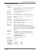
Chapter 1 - Introduction and Description Technical Specifications The ModemModule meets the following specifications: Data Rates Client-to-Server DataComm: supports enhanced V.34 (33.6K), V.32bis (14.4K), V.32 (9600), V.22bis (2400), or slower speed connection for download speeds, and upload speeds to 33.6 Kbps via enhanced V.34.
ModemModule Developer’s Guide Carrier Frequencies ITU-T V.23 (1200 bps) Transmit originate: Receive originate: Transmit answer: Receive answer: Carrier Frequencies ITU-T V.
Chapter 1 - Introduction and Description Physical Dimensions Figure 1-2 illustrates the the physical dimensions of the MT3334SMI. .286 [7,26] 1.861 [47,27] .079 TYP. [2,01] .079 [2,01] 1.045 [26,54] .995 [25,27] .050 [1,27] .050 [1,27] 1.861 [47,27] 2.019 [51,28] 2.256 [57,3] .354 [8,99] .062 [1,57] .945 REF. [24] .118 [3] MAXIMUM COMPONENT HEIGHT SOLDER SIDE 2.550 [64,77] .228 [5,8] .063 [1,6] .020 ± .0002 SQUARE [0,51] .310 [7,87] Figure 1-2.
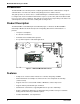
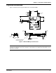
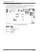
ModemModule Developer’s Guide Test/Demo Board Specifications The ModemModule Test/Demo Board kit includes a modem module, a power transformer for the test board, and a diskette (this Developer’s Guide manual, etc.). Figure 1-3 illustrates the demo/test board and Figure 1-4 illustrates the Test/Demo board block diagram. S1 LED 4 J7 DS1 LED 3 LED 2 LED 1 J1 J4 J3 J5 J6 J2 Figure 1-4. MT3334SMI Test/Demo Board 10 Designation Function DS1 J1 J2 J3, J6 J4, J5 J7 LED1-LED4 S1 Speaker 25-Pos.
Chapter 1 - Introduction and Description Test/Demo Board Block Diagram Power Switch Power Supply Speaker DS1 Volume Control Socket Modem Transceiver (RS-232) Power Connector DB-25 RS-232 LEDs Tip/Ring Fuse RJ-11 Connector Figure 1-4.
ModemModule Developer’s Guide MT3334SMI Pin-out The MT3334SMI uses a 20-pin interface to provide an on-board DAA with tip and ring connections, audio circuit for call-progress monitoring, LED driver for call status annunciation, and serial interface via TTL level signals.
Chapter 1 - Introduction and Description Typical Application The table below shows the MT3334SMI pinouts and Figure 1-6 illustrates a typical OEM application.
ModemModule Developer’s Guide MT3334SMI Design Considerations This section discusses hardware considerations, PC board layout considerations, and Telecom labeling requirements. Hardware Considerations Disclaimer: Multi-Tech Systems makes no warranty claims for vendor product recommendations listed below. Other vendor products may or may not operate satifactorily.
Chapter 1 - Introduction and Description Safety: All creepages and clearances for the MT3334SMI have been designed to meet requirements of safety standards EN60950 and IEC950. The requirements are based on a working voltage of 250V. When the recommended DAA circuit interface is implemented in a third party design all creepage and clearance requirements must be strictly adhered to. The third party safety design must be evaluated by the appropriate national agency per the required specification.
ModemModule Developer’s Guide MT3334SMI Placement Figure 1-8 illustrates where to place the MT3334SMI on a typical Motherboard. It must be placed so that the analog end is near the phone jack. 0.035 [0.889] Drill with 0.060 [1.524] Pad .0787 TYP [2] 0.125 [3.175] Non-Plated A to D Barrier (Shown for Reference Only) 1.732 [44] .750 [19.05] .145 [3.683] .945 [24.003] B or C Note: The locking end of C should go in the Motherboard.
Chapter 1 - Introduction and Description Telecom Labeling Requirements FCC regulations require labeling of registered Telephone and Data Terminal Equipment in accordance with Part 68 Subpart D. There are two options available for labeling of the device containing the MT5634SM modem module. The first option would be to use the registration number assigned to Multi-Tech Systems, Inc. by the FCC as explained in Section 68.300 below and shown in the sample label.
ModemModule Developer’s Guide Reregistration (From Form 730 Application Guide Appendix C-2) http://www.fcc.gov/formpage.html Private label distributors may obtain a registration number in their own name. In this case, a reregistration filing is made with the submission of Exhibit B, a copy of a letter from the original registrant to the applicant giving permission for the reregistration and a willingness to provide the applicant with any technical support.
Chapter 2 - AT Commands, S-Registers, and Result Codes
ModemModule Developer’s Guide Introduction The AT commands are used to control the operation of your modem. They are called AT commands because each command must be preceded by the characters AT to get the ATtention of the modem. AT commands can be issued only when the modem is in command mode or online command mode. The modem is in command mode whenever it is not connected to another modem. The modem is in data mode whenever it is connected to another modem and ready to exchange data.
Chapter 2 - AT Commands, S-Registers, and Result Codes Command: Bn Values: Default: Description: B0 B1 B2 B3 B15 B16 Communication Standard Setting n = 0–3, 15, 16 1 and 16 Select ITU-T V.22 mode when modem is at 1200 bps. Select Bell 212A when modem is at 1200 bps. Deselect V.23 reverse channel (same as B3). Deselect V.23 reverse channel (same as B2). Select V.21 when the modem is at 300 bps. Select Bell 103J when the modem is at 300 bps.
ModemModule Developer’s Guide Command: In Values: Default: Description: I0 I1 I2 I3 I4 I5 I9 I11 Information Request n = 0–5, 9, 11 None Display default speed and controller firmware version. Calculate and display ROM checksum (e.g., 12AB). Check ROM and verify the checksum, displaying OK or ERROR. Display default speed and controller firmware version. Display firmware version for data pump (e.g., 94). Display the board ID: software version, hardware version, and country ID Display the country code (e.g.
Chapter 2 - AT Commands, S-Registers, and Result Codes Command: Sr? Values: Default: Description: Read Register Value r = S-register number None Read value of register Sr and display it in 3-digit decimal form. E.g., S2? gives the response 043. Command: T Values: Default: Description: Tone Dialing P, T T Configures the modem for DTMF (touch-tone) dialing. Dialed digits are tone dialed until a P command or dial modifier is received.
ModemModule Developer’s Guide Command: &Fn Values: Default: Description: &F0 Load Factory Settings n=0 None Load factory settings as active configuration. Note: See also the Z command. Command: &Gn Values: Default: Description: &G0 &G1 &G2 V.22bis Guard Tone Control n = 0, 1, or 2 0 Disable guard tone. Set guard tone to 550 Hz. Set guard tone to 1800 Hz. Note: The &G command is not used in North America.
Chapter 2 - AT Commands, S-Registers, and Result Codes Command: &Zy=x Store Dialing Command Values: y = 0–3 (callback security disabled) or 0–29 (callback security enabled) x = Dialing command Default: None Description: Stores dialing command x in memory location y. Dial the stored number using the command ATDS=y. See also the #CBSn command. For callback security options, see Chapter 6.
ModemModule Developer’s Guide Command: \Nn Values: Default: Description: \N0 \N1 \N2 \N3 \N4 \N5 \N7 Error Correction Mode Selection n = 0–5, or 7 3 Non-error correction mode with data buffering (buffer mode; same as &Q6). Direct mode. MNP reliable mode. If the modem cannot make an MNP connection, it disconnects. V.42/MNP auto-reliable mode. The modem attempts first to connect in V.42 error correction mode, then in MNP mode, and finally in non-error-correction (buffer) mode with continued operation. V.
Chapter 2 - AT Commands, S-Registers, and Result Codes Command: %DCn AT Command Control Values: n = 0 or 1 Default: 0 Description: %DC0 The modem responds to AT commands. %DC1 The modem ignores AT commands. Note: The modem will respond to AT%DC for 10 seconds after power-up. Command: %En Values: Default: Description: %E0 %E1 %E2 Fallback and Fall Forward Control n = 0, 1, or 2 2 Disable fallback and fall forward. Enable fallback, disable fall forward. Enable fallback and fall forward.
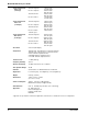
ModemModule Developer’s Guide S-Registers Certain modem values, or parameters, are stored in memory locations called S-registers. Use the S command to read or to alter the contents of S-registers (see previous section). Register Unit Range Default Description S0 1 ring 0, 1–255 1 Sets the number of rings until the modem answers. ATS0=0 disables autoanswer completely. S1 S2 1 ring 0–255 decimal 0–127 0 43 (+) Counts the rings that have occurred. Sets ASCII code for the escape sequence character.
Chapter 2 - AT Commands, S-Registers, and Result Codes S43 decimal 0–1 1 S48 decimal 7 or 128 7 For testing and debugging only. Enables/disables V.32bis start-up auto mode operation. 0 = disable; 1 = enable. Enables (7) or disables (128) LAPM negotiation. The following table lists the S36 and S48 configuration settings for certain types of connections.
ModemModule Developer’s Guide Result Codes In command mode your modem can send responses called result codes to your computer. Result codes are used by communications programs and can also appear on your monitor.
Chapter 3 - Class 1 Fax Commands
ModemModule Developer’s Guide Introduction The Service Class 1 standard (EIA/TIA-578) defines the commands that a PC user may issue to configure and control a fax/data modem, and the responses (result codes) that the fax/data modem may issue in response to those commands. The Class 1 standard provides the basic services needed to support Group 3 fax operation. Support of the 1988 CCITT (ITU-T) T.30 recommended procedures for session management and the T.
Chapter 3 - Class 1 Fax Commands Table 3-1. Fax MOD (Modulation) Parameter Values Value 3 24 48 72 73 74 96 97 98 121 122 145 146 Modulation V.21 ch.2 V.27ter V.27ter V.29 V.17 V.17 w/st V.29 V.17 V.17 w/st V.17 or V.33 V.17 w/st V.17 or V.33 V.
ModemModule Developer’s Guide Command: Function: Values: Default: Result Codes: Description: +FCLASS= Select Service Class 0, 1, 2 0 (data mode) OK if the command is accepted; ERROR if the parameter value is out of range. This command configures the Service Class for the modem.
Chapter 3 - Class 1 Fax Commands Command: Function: Values: Default: Result Codes: Description: +FRS=? Display the range of stop-transmission-and-wait period values
ModemModule Developer’s Guide Command: Function: Values: Default: Result Codes: Description: +FRM=? Display the valid range of receive data modulation values = 3, 24, 48, 72, 73, 74, 96, 97, 98, 121, 122, 145, 146 3 (V.21 ch.2 @ 300 bps) the current value range supported by the modem. The +FRM=? command causes the modem to display the current modulation for receive data spcified by the +FRM= command.
Chapter 3 - Class 1 Fax Commands Flow Control XON/XOFF flow control is used by the ModemModule to match the PC-to-modem data rate to the line signaling rate. XON/XOFF flow control is mandatory and RTS/CTS flow control is optional per the Class 1 standard. There is currently no Class 1 command for setting the flow control method, and no means to read the current flow control method in use. The PC is responsible for matching the modem's default flow control method.
ModemModule Developer’s Guide Table 3-2. Single-Page Class 1 Transmit Example Command Respone AT+FCLASS=1 ATD OK CONNECT OK AT+FRH=3 AT+FRH=3 AT+FRH=3 AT+FTH=3 Action by Remote PC Answers Sends CED, V.21 Sends HDLC flags Send CSI packet Send NSF packet Send CSI packet Check FCS CONNECT frame data OK Detect flags Get DIS Send DIS packet Get CRC Accept FCS Check FCS NO CARRIER Detect loss of carrier Drop carrier Send V.
Chapter 3 - Class 1 Fax Commands Table 3-3. Single-Page Class 1 Answer & Receive Example Command AT+FCLASS=1 Respone Action by Remote PC OK RING Set Class to 1 Detect Ringing Dial, send CNG CONNECT Off hook, Send CED, Send V.
ModemModule Developer’s Guide 40 MT3334SMI
Chapter 4 - Class 2 Fax Commands
ModemModule Developer’s Guide Introduction This chapter provides fax software developers with specific Class 2 fax command protocol information to be used in development with Lucent L33xVCS modem chip set. It is assumed that users have an understanding of ITU-TSS T.30 and T.4 concepts. The “fax command protocol” is defined here as the set of AT Commands used to control the sending/receiving of faxes.
Chapter 4 - Class 2 Fax Commands 50 - 69 Transmit phase D hang-up codes 52: 53: 54: 55: 56: 57: No response to MPS repeated 3 times Invalid response to MPS No response to EOP repeated 3 times Invalid response to EOP No response to EOM repeated 3 times Invalid response to EOM 70 - 89 Receive phase B hang-up codes 90 - 99 Receive phase C hang-up codes 90: Unspecified receive phase C error 100 - 119 Receive phase D hang-up codes 100: Unspecified receive phase D error 120 - 255 Reserved codes +FBOR Data B
ModemModule Developer’s Guide +FDCC Fax Capability Parameters Command syntax: Response syntax: +FDCC=VR,RB,WD,LN,DF,EC,BF,ST VR,BR,WD,LN,DF,EC,BF,ST Valid values: +FDCS VR: Vertical resolution 0: Normal, 98 lpi 1: Fine, 196 lpi BR: Bit rate 0: 2400 bits/s V.27ter 1: 4800 bits/s V.27ter 2: 7200 bits/s V.29 or V.17 3: 9600 bits/s V.29 or V.17 4: 12000 bits/s V.33 or V.17 5: 14400 bits/s V.33 or V.
Chapter 4 - Class 2 Fax Commands 4: 12000 bits/s V.33 or V.17 5: 14400 bits/s V.33 or V.
ModemModule Developer’s Guide DF: Data compression format. 0: 1-D modified Huffman EC: Error correction. 0: Disable ECM BF: Binary file transfer. 0: Disable BFT ST: Scan time/line. 0: 1: 2: 3: 4: 5: 6: 7: +FDR VR = normal 0 ms 5 ms 10 ms 10 ms 20 ms 20 ms 40 ms 40 ms VR = Fine 0 ms 5 ms 5 ms 10 ms 10 ms 20 ms 20 ms 40 ms Begin or Continue Phase C Receive Data Command syntax: +FDR This command will initiate a transition to Phase C data reception.
Chapter 4 - Class 2 Fax Commands +FK Session Termination Command syntax: +FK This command causes the modem to terminate the session in an orderly manner. +FLID Local ID String Command syntax: +FLID=”” Valid values: ASCII string can be up to 20 characters Response syntax: +FLID=? Return value: (20),(32 - 127) +FLNFC Page Length Format Conversion Command syntax: +FLNFC= 0: Disables mismatch checking.
ModemModule Developer’s Guide +FPTS Page Transfer Status Command syntax: +FRBC +FPTS= 1: MCF Page good 2: RTN Page good; retrain requested 3: RTP Page good; retrain requested. Phase C Receive Data Block Size Command syntax: +FRBC= 0: Stream mode, Phase C data is terminated by . +FREL Phase C Received EOL Alignment Command syntax: +FREL= 0: Indicates that EOL patterns are aligned as received (Default).
Chapter 4 - Class 2 Fax Commands +FDIS Reports DIS Frame Information Syntax: +FDIS:VR,BR,WD,LN,DF,EC,BF,ST Usage: Reports remote FAX capabilities and intentions. The subparameters are described in the +FDCS command description. +FET Post Page Message Response Syntax: +FET: Usage: Generated by the receiving modem after the end of Phase C reception, on receipt of the postpage message from the transmitting station. The codes are described in the +FET command description.
ModemModule Developer’s Guide 50 MT3334SMI
Chapter 5 - Remote Configuration
ModemModule User Guide Introduction Remote configuration is a network management tool that allows you to configure modems anywhere in your network from one location. With password-protected remote configuration, you can issue AT commands to a remote MT3334SMI for maintenance or troubleshooting as if you were on-site. Basic Procedure The following steps are valid regardless of whether the connection is established by the local or the remote Multi-Tech modem. 1.
Chapter 5 - Remote Configuration Changing the Remote Escape Character To increase security, you can change a remote modem’s remote configuration escape character. The remote configuration escape character is stored in register S9. The factory default is 37, which is the ASCII code for the percent character (%). Setting S9 to 0 (zero) disables remote configuration entirely—but if you do this remotely, you won’t be able to change it back remotely! 1.
ModemModule User Guide 54 MT3334SMI
Chapter 6 - Troubleshooting
ModemModule Developer’s Guide Introduction Each time you turn on your modem, it performs an automatic self-test to ensure proper operation. Your modem also has three diagnostic tests: local analog loopback, remote digital loopback, and local digital loopback. These ITU-T V.54 loopback tests isolate telephone circuit and transmission problems. In a loopback test, data from your computer loops through the circuits of your modem and/or a remote modem before it appears on your monitor.
Chapter 6 - Troubleshooting 6. Your modem passes this test if the data received on your monitor are the same as the data entered from your keyboard. If different data appear on your monitor, your modem is probably causing the problem, though it could also be your computer. If your modem passes this test, but you are receiving errors while on line, the remote modem or the phone line could be at fault. Remote Digital Loopback Test (V.
ModemModule Developer’s Guide Local Digital Loopback Test (V.54 Loop 2) The local digital loopback test is identical to the remote digital loopback test with one exception. Instead of using your modem to signal a remote modem to place itself in digital loopback mode, your modem is placed in digital loopback mode while the remote modem is not. Data is entered and transmitted from the remote modem, sent across the phone line to your modem, and looped back to the remote modem.
Chapter 7 - Upgrade Procedure
ModemModule Developer’s Guide Introduction Your ModemModule is controlled by semi-permanent firmware that is stored in flash memory. Firmware is nonvolatile; it remains stored in memory when the modem is turned off. However, it can be changed by either the manufacturer or the user as bugs are fixed or new features are added. Since the firmware is stored in flash memory, you can upgrade it yourself in a few minutes by using the following procedures.
Chapter 7 - Upgrade Procedure Multi-Tech BBS 1. Run your favorite terminal program and dial in to the Multi-Tech BBS at 800-392-2432 (North America) or 612-785-3702 (local and international). If you followed the download test in the Quick Start chapter, your terminal program should already be configured for the Multi-Tech BBS. 2. When the BBS welcome screen is displayed, type your first name, last name, and password following the prompts.
ModemModule Developer’s Guide Step 4: Extract the Upgrade Files 1. Move the downloaded upgrade file to a temporary directory or folder on your hard disk. 2. The file is a self-extracting archive. Extract the files by typing the upgrade file name in DOS or double-clicking it in Windows. The extracted files include a .HEX file, which contains the upgrade data, and one flash program each for DOS, Windows 3.1/95/98, and Windows NT.
Appendixes
ModemModule Developer’s Guide Appendix A - Regulatory Agency Compliance FCC Regulations for Telephone Line Interconnection 1. This equipment complies with Part 68 of the Federal Communications Commission (FCC) rules. On the outside surface of this equipment is a label that contains, among other information, the FCC registration number. This information must be provided to the telephone company. 2.
Appendixes Canadian Limitations Notice: NOTICE: The Industry Canada label identifies certified equipment. This certification means that the equipment meets certain telecommunications network protective, operational and safety requirements. The Industry Canada label does not guarantee the equipment will operate to the user’s satisfaction. Before installing this equipment, users should ensure that it is permissible to be connected to the facilities of the local telecommunications company.
ModemModule Developer’s Guide EMC, Safety and Terminal Directive Compliance The CE mark is affixed to this product to confirm compliance with the following European Community Directives: Council Directive 89/336/EEC of 3 May 1989 on the approximation of the laws of Member States relating to electromagnetic compatibility.
Appendixes Appendix B - Multi-Tech Flash Programming Protocol Introduction This appendix describes the protocol by which the modems are flash programmed. The information in this section is provided for the exclusive use of the users of modems by Multi-Tech Systems, Inc. Such users have the right to use, modify, and incorporate this code into other products provided they include the Multi-Tech Systems, Inc. notice and the associated copyright notice with any such product.
ModemModule Developer’s Guide Program Sequence DTE Modem ATFLP\r Request to the modem to program G Modem is ready for next program packet [Length High] High byte of data packet length [Length Low] Low byte of data packet length Packet lengths can be up to 4096 bytes in size for most boot code versions (see section 3.
Appendixes 3.3. The packets sent to the modem must be presorted by address and aligned on 128 byte boundaries (ie. each packet must start on an address that is a multiple of 128). 3.4. The packets should also be a minimum of 128 bytes with the non-programmed bytes set to the hex value of FF. 3.5. The packets sent to the modem must not span a 4K boundary (ie. start the packet before it and go over the boundary in the middle of the packet). 3.6.
ModemModule Developer’s Guide Extended Address Record Char Pos Field Type Value Description 1 Record Start “:” 2-3 Data Byte Count “02 Always 2 bytes for this record type 4-7 Address “0000” Not used for this record type (must be zero) 8-9 Record Type “02” Extended Address Record 10-13 Extended Address “EEEE” Top 16 bits of 20 bit address, most significant byte first 14-15 Checksum “ZZ” Zero minus the two’s complement addition of all data hex values 16-17 End of Line “\r\n” Car
Index Index A Abort timer ............................................................. 28 Analog loopback test ............................................. 56 Answer command ................................................. 20 Asynchronous Communications Mode command . 24 AT Command Control command ........................... 27 AT commands ....................................................... 20 #S ............................................................... 27, 52 #S= .............................
ModemModule Developer’s Guide Class 1 fax commands Sample sessions ............................................... 37 Class 2 Fax commands Implementation .................................................. 42 Overview ............................................................ 42 Comma, setting pause time ................................... 28 Command mode .................................................... 20 Command string ....................................................
Index MT3334SMI Design Considerations ....................................... 14 Features .............................................................. 6 Product overview ................................................. 6 Technical specifications ....................................... 7 Multi-Tech BBS ...................................................... 61 Multi-Tech flash programming ............................... 67 Multi-Tech web site ................................................
ModemModule Developer’s Guide U Upgrading the modem ........................................... 60 V V.22 mode ............................................................. 21 V.22bis Guard Tone Control command .................. 24 V.25 data calling tone ..................................... 26, 28 V.34 modulation, enabling ..................................... 28 V.42 error correction .............................................. 26 V.42bis data compression ..................................... 26 V.