MultiModemISI Hybrid Series Models ISIHP- 2S/2U/4S/4U/4SD User Guide
MultiModemISI Hybrid Model ISIHP-2S/2U/4S4U4SD User Guide 88311551Revision B All rights reserved. This publication may not be reproduced, in whole or in part, without prior expressed written permission from Multi-Tech Systems, Inc. All rights reserved. Copyright © 1999 by Multi-Tech Systems, Inc. Multi-Tech Systems, Inc. makes no representation or warranties with respect to the contents hereof and specifically disclaims any implied warranties of merchantability or fitness for any particular purpose.
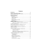
Contents Introduction 4 Welcome and Product Description .................................................... 4 Peripiheral Component Interconnect (PCI) ....................................... 8 Communication Protocols ................................................................. 9 Hardware Installation Introduction ........................................................................................... 12 Computer Requirements ........................................................................
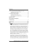
Introduction NetWare Connect (Novell) Driver Installation (2S/2U only) ..................... 61 Configuring Ports for NetWare Connect .......................................... 61 Removing the Driver (Novell) ......................................................... 61 SCO Open Server 5 Driver Installation ...................................................... 62 MultiTech Installation Script ........................................................... 63 Activating Ports in SCO Open Server 5 ...............
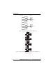
Introduction analog calls are detected, they are automatically connected to one of the four V.90 modems on the ISIHP board. In this way, these hybrid cards can handle either ISDN calls or analog modem calls. Although the ISIHP-2S/2U contains four ISDN TA ports and four analog modem ports, only four ports can be active at any one time (because only four B-channels are present). See Figure 1-1. The ISIHP-4S/4U works like the ISIHP-2S/2U but contains four terminal adapters and eight V.90/K56flex modems.
Introduction ISDN Com Ports 5 Modem 1 2 TA 6 Modem 7 Modem 3 4 TA 8 Modem 3456 RJ-45 jack Line 1 3456 RJ-45 jack Line 2 Figure 1-1: Modems and Terminal Adapters of ISIHP-2S/2U 9 Modem 1 2 TA 10 Modem 11 Modem 3 4 TA 12 Modem 13 Modem 5 6 TA 14 Modem 15 Modem 7 8 TA 16 Modem 3456 RJ-45 Jack 3456 RJ-45 Jack 3456 RJ-45 Jack 3456 RJ-45 Jack Figure 1-2: Modems and Terminal Adapters of ISIHP-4S/4U (for ISIHP-4SD, no modems are present) 6 MultiModemISI Hybrid Seri
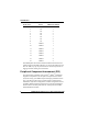
Introduction From the perspective of the server PC, the ISIHP-2S/2U is an eightport serial card with eight devices permanently attached to the serial ports (Figure 1-1). The first four ports are the two terminal adapters, each of which appear as two ports. The remaining four ports are the four central site modems. The following chart summarizes the correlation of ports and devices.
Introduction 4S/4U Port # Device ISDN Line Number 1 2 3 4 5 6 7 8 TA TA TA TA TA TA TA TA 1 1 2 2 3 3 4 4 9 Modem 1 10 Modem 1 11 Modem 2 12 Modem 2 13 Modem 3 14 Modem 3 15 Modem 4 16 Modem 4 This ISIHP Quick Start Guide contains installation instructions and technical support information. Because its written for audiences with basic PC skills, step-by-step instructions for such basic operations as logging in and file editing are not included.
Introduction Communication Protocols for ISIHP Ports Ports on the ISIHP card can be associated with different protocols, as follows: Auto-Protocol. Modem or terminal adapter automatically negotiates with host to operate using the hosts current protocol. Central Site Modem. Common designation for analog modems built into the ISIHP card. These are V.90 modems.
Introduction 10 MultiModemISI Hybrid Series, ISIHP-2S/2U/4S/4U/4SD
Hardware Installation Hardware Installation MultiModemISI Hybrid Series, ISIHP-2S/2U/4S/4U/4SD 11
Hardware Installation Introduction This section describes how to install the ISIHP server card into the PCI bus on your personal computer, which involves Opening your PC Installing the card into the PC Computer Requirements Pentium-based PC or compatible with PCI bus architecture Microsoft Windows 95, Windows 98, Windows NT version 4.0, SCO Open Server version 5.
Hardware Installation Do not use the telephone to report a gas leak in the vicinity of that leak. Ports that are connected to other apparatus are defined as SELV. To ensure conformity to EN 41003, ensure that these ports are connected only to the same type on the other apparatus. Hardware Installation Procedure 1. Before handling the ISIHP card, discharge any static in your body by touching a piece of grounded metal such as the computer chassis. 2.
Hardware Installation a Intelligent Serial Interface Hybrid (ISDN/POTS) Cards (Side View) aa V.110 Daughter Card ISIHP-2S International V.110 Daughter Card Modem Card ISIHP-2U U.S. Domestic V.110 Daughter Card Modem Card ISIHP-4S/4U Figure 1-3: ISIHP Cards; Side View (on ISIHP-4SD, right daughter card is not present) 4. To avoid damaging the ISIHP-2S/2U and your PC, make sure your computer and any peripheral equipment connected to it are turned off.
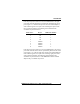
Hardware Installation 9. Connect the ISIHP-2S/2U to your ISDN telephone wall jack with the provided modular telephone cable. U Interface S Interface S/T Interface NT1 Device ISIHP -2S ISDN line enters building Figure 1-4: ISDN Interfaces at Customer Premises Note: The ISIHP communicates over ISDN lines. If you dont have a standard modular jack near your computer, you should install one or have one installed by your telephone company.
Hardware Installation LED Indicators The mounting brackets for the four ISIHP cards are similar, but the LEDs are labeled differently. Below, and on the next page, are graphics for each bracket along with descriptions of the LED indicators. ISIHP-4U LEDs (one LED per BRI) 1 2 3 4 Flashes between OFF and RED to indicate that neither SPID for that ISDN line has been verified. Flashes between RED and GREEN to indicate that one SPID is correct.
Hardware Installation ISIHP-2S LED Indicators B1 LED Indicator When lit, indicates active or voice connection on B-channel 1. When lit, indicates active or voice connection on B-channel 2.
Hardware Installation ISIHP-2U LED Indicators P LED Indicator Indicates U interface status connection. Controlled by NT-1, which converts S/T interface (4-wire ISDN) to U interface (2-wire ISDN). D P When U interface and S/T interface are NOT active, LED remains off. LINE 1 Flashes 8 times/second (8 Hz)U interface is attempting to activate. Flashes once/second (1 Hz)U interface is active; S/T interface is not fully active.
Software/Driver Installation Software Installation MultiModemISI Hybrid Series, ISIHP-2S/2U/4S/4U/4SD 19
Software/Driver Installation (Windows NT) Installing the ISIHP in Windows NT 3.51/4.0 The following procedure describes how to install the ISIHP card in a system operating Microsoft Windows NT 3.51 or 4.0 for use with Remote Access Service (RAS) server and other communications/fax server type applications. These procedures refer to both 3.51 and 4.0. 1. Install the ISIHP in an available PCI slot as described in the installation section of this manual. 2. Turn on the computer. 3.
Software/Driver Installation (Windows NT) 5. The Insert Disk dialog box appears. Insert the MultiModem ISI Driver for Windows NT diskette and click OK. 6. The Select OEM Option dialog box appears. Click OK.
Software/Driver Installation (Windows NT) A transient dialog box will appear while the setup program is loaded from the diskette to the PC hard drive. 7. The ISI Cards dialog box appears. Click Add. 8. Then this ISI Cards dialog box appears. Select the starting port (usually port 3).
Software/Driver Installation (Windows NT) 9. The ISI Cards dialog box appears again showing the port assignment. Click Add to add additional cards and repeat step 8. After the last ISIHP card has been added, click Close.
Software/Driver Installation (Windows NT) 10. The file copies and Multi-Tech ISIHP Adapter appears in the Network Adapters box. Click Close. 11. When this dialog box appears, click Yes to reboot your system. The ISIHP-2S/2U now is installed in Windows NT. Installing TAs & Modems to COM Ports in Windows NT To install terminal adapters: 1. In the Control Panel, double-click the Modems icon. 2. The Modem Properties dialog box appears. Click Add.
Software/Driver Installation (Windows NT) 3. The Install New Modem dialog box appears. Check the box marked Don't detect my modem; I will select it from a list and click Next. 4. The Install New Modem dialog box appears. Click Have Disk.
Software/Driver Installation (Windows NT) 5. The Install From Disk dialog box appears. Click OK (diskette should still be in drive). 6. The Install New Modem dialog box appears. From the Models list, select an ISDN protocol (Auto-Protocol, ML-PPP, PPP, V.120, or X.75, depending on your application). ( See description of protocols in the Introduction chapter of this manual.) Then click Next. 7. The Install New Modem dialog box appears.
Software/Driver Installation (Windows NT) 8. After the terminal adapters install, click Finish to return to the General tab to view COM port assignments (and make changes if necessary). Now you are ready to install the modems. To install modems: {does not apply to -4SD} 1. In the General tab, click Add.
Software/Driver Installation (Windows NT) 2. The Install New Modem dialog box appears. Check the box marked Don't detect my modem; I will select it from a list. Then click Next. 3. The Install New Modem dialog box appears. From the Models list, select Central Site Modems for the modems. Then click Next.
Software/Driver Installation (Windows NT) 4. Select the ports that correspond to the last four ports of the ISIHP2S/2U card OR the last eight ports of the ISIHP-4S/4U card. Click Next. The modems install to the selected COM ports. 5. After the modems install to the ports, click Finish to return to the General tab.
Software/Driver Installation (Windows NT) 6. To view COM port assignments and make necessary changes, use the Modem Properties dialog box. 7. Close the Modems Properties dialog box. The message below appears asking if you want to configure dial-up networking. Click Yes.
Software/Driver Installation (Windows NT) 8. The Remote Access Setup dialog box appears. Click Add. 9. Each COM port appears in a separate Add RAS Device dialog box. To add the highlighted device, click OK. 10. The Remote Access Setup dialog box displays again. Repeat steps 7 and 8 until all devices are added. 11. When all devices have been added, click Continue.
Software/Driver Installation (Windows NT) 12. After the bindings have been reviewed and stored, the message below appears, click Yes. After re-booting, the ISI Cards icon appears in the Control Panel. icon You are now ready to configure the terminal adapter. See the section,Configuring the Terminal Adapter, on page 49. I/O Addresses and IRQ Codes Unlike many modem products, the ISIHP has no DIP switch for I/O addresses and no jumper to determine the IRQ code.
Software/Driver Installation (Windows NT) (for Windows NT) click on Start, Settings, Control Panel and select the ISI Cards icon; or click on Start, Programs, Administrative Tools (Common), Windows NT Diagnostics, Resources; (for Windows 95) click on Start, Settings, and Control Panel. From the Control Panel, click on System icon and then the Device Manager tab. From there, click on the Computer icon at the top of the Device Manager window. The Computer Properties dialog box will appear.
Software/Driver Installation (Windows 95/98) Installing the ISIHP in Windows 95 and Windows 98 This section describes how to install the ISIHP in systems operating Microsoft Windows 95 or Windows 98 to use with a Remote Access Service (RAS) server and other communications/fax server type applications. Windows 95 Installation 1. After installing the ISIHP in an available PCI slot, turn on the computer. 2. Windows 95 automatically detects the ISIHP card.
Software/Driver Installation (Windows 95) 5. To view the COM ports, click Control Panel and double-click System. In the System Properties dialog box in Device Manager, the MultiTech PCI ISI Card appears under Multi Port. To view ports, click Ports (COM & LPT). Click OK to close.
Software/Driver Installation (Windows 95) To Remove the ISIHP Card &Drivers in Windows 95 To remove the ISIHP card: 1. Click Start, Settings, Control Panel, and then System. 2. The System Properties dialog box appears. Click the Device Manager tab. 3. Click Multi Port Adapter and select MultiTech PCI ISI Card, and then click Remove. To remove the drivers: 1. Click Start, Settings, Control Panel, and then double-click Add/ Remove Programs. 2. Select MultiTech ISI Card and then click Add/Remove.
Software/Driver Installation (Windows 98) 4. In the next Wizard dialog box, select Search for the best driver for your device. (Recommended). Then click Next. 5. In the next Wizard dialog box, make sure Floppy disk drives is checked. Insert the MultiModem ISI Driver for Windows 95/98 diskette. Then click Next and the system locates the file.
Software/Driver Installation (Windows 98) 6. When this Wizard dialog box appears, click Next. 7. Windows then installs the device driver for the ISIHP card. When this dialog box appears, click Finish. Windows 98 will now detect and create COM ports (for ISIHP2S/2U/4SD, 8 ports are made; for ISIHP-4S/4U 16 ports are made). 8. After the COM parts have been created, you must re-boot your PC (remove the diskette from the floppy drive before re-booting). 9.
Software/Driver Installation (Windows 98) The MultiTech PCI ISI Card is located under Multi Port Adapter. Click Ports (COM & LPT) to view the ports. Click OK to close. To Remove the ISIHP Card and Drivers in Windows 98 To remove the ISIHP card: 1. Re-boot your computer. 2. Click Start, Settings, Control Panel, and then System. 3. The System Properties dialog box appears . Click the Device Manager tab. 4. Click Multi Port Adapter and select MultiTech ISIHP-2S/2U 2BRI/4 56K Hybrid Card. Then click Remove.
Software/Driver Installation (Windows 98) 2. Select MultiTech ISI Card and then click Add/Remove. Installing TAs & Modems to COM Ports in Windows 95 /98 To install terminal adapters: 1. Click Start, Settings, Control Panel, and then double-click the Modems icon. 2. If no modems are currently installed, the Install New Modem dialog box appears. Check the box marked Don't detect my modem; I will select it from a list. Then click Next.
Software/Driver Installation (Windows 98) Click Add and the Install New Modem dialog box will appear. Check the box marked Don't detect my modem; I will select it from a list. Then click Next. 3. The Install New Modem dialog box appears. Insert diskette labeled MultiModem ISI Driver for Windows 95 & Netware AIO and click Have Disk.
Software/Driver Installation (Windows 98) 4. The Install From Disk dialog box appears. Click OK. 5. The Install New Modem dialog box appears. Select a protocol (depending on your application) from the Models list; then click Next. 6. The Install New Modem dialog box appears. Select the port that corresponds to the lowest numbered port of the ISIHP card. Any ports that had been installed before installing the ISIHP card are numbered lower than the ports of the ISIHP card. Click Next.
Software/Driver Installation (Windows 98) 7. Windows will install the first terminal adapter. Click Next.
Software/Driver Installation (Windows 98) 8. After the terminal adapter installs, click Finish to return to the General tab to view COM port assignments (and make changes if necessary). 9. 44 Click Add and repeat installation steps 28 to install terminal adapters to the first four ports of the ISIHP-2S/2U (OR the first eight ports of the ISIHP-4S/4U/4SD). After the terminal adaptershave been installed, you are ready to install the modems.
Software/Driver Installation (Windows 98) To install modems (Windows 95/98): {not applicable to -4SD} 1. In the General tab, click Add. 2. The Install New Modem dialog box appears. Check the box marked Don't detect my modem; I will select it from a list. Then click Next.
Software/Driver Installation (Windows 95/98) 3. The Install New Modem dialog box appears. Insert the driver diskette labeled MultiModem ISI Driver for Windows NT. Then click Have Disk. 4. The Install from Disk dialog box appears. Click OK. 5. The Install New Modem dialog box appears. From the Models list, select Central Site Modems for the modems. Then click Next.
Software/Driver Installation (Windows 95/98) 6. The Install New Modem dialog box appears. Select the numbered port corresponding to the first modem of the ISIHP card. Click Next. The modem installs to the COM port. 7. After the modem installs to the port, click Finish.
Software/Driver Installation (Windows 95/98) 8. Return to the General tab to view COM port assignments (and make changes if necessary). 9. Click Add and repeat installation steps 28 to install modems to the last three ports of the ISIHP-2S/2U (OR the last seven ports of the ISIHP-4S/4U). Now you are ready to configure the terminal adapters.
Software/Driver Installation (Windows 95/98) Removing the Driver (Windows 95 only) 1. Click Settings, Control Panel, and then double-click Add/ Remove Programs. 2. From the list box, select ISICOM Driver. 3. Click Add/Remove and follow screen instructions. Configuring the Terminal Adapter Introduction North American users must configure the terminal adapter to match network switch type, the service profile identifier (SPID), and the directory number (DN).
Software/Driver Installation (Windows 95/98) central office. You can set the TA to NET3, AT&T 5ESS, NT DMS100, or US National ISDN-1. If you don't know the switch type, get the information from the local phone company. AT command: !CO= SPIDs and DNs ________________________ The TA must be configured with the Service Profile Identifier (SPID). The SPID, assigned by the local phone company, is for the specific BRI line where TA is attached. The SPID field is empty prior to configuration.
Software/Driver Installation Persistent DTR Dialing __________________ A high DTR (Data Terminal Ready) signal on the serial port indicates that your computer or terminal is ready to communicate with your TA. DTR normally goes high when a communication program starts or is ready to dial. Persistent DTR dialing enables the TA to automatically redial the number stored in memory location 0 whenever DTR is high, and the serial port does not have an active call. You can enable or disable this feature.
Software/Driver Installation X.75 Protocol The ISIHP uses layer 2 of the X.75 protocol as an error correction protocol on the B-channel. Stored Numbers ________________________ The TA can optionally store as many as 10 phone numbers, up to 20 characters each. AT command: &Z= Dialing Stored Numbers _________________ The TA can dial a number previously stored in directory number n using the &Zn=x command. AT command: e.g., DS3 ISDN TA Configuration Utility 1.
Software/Driver Installation 10. The Welcome dialog box appears. Click Next.
Software/Driver Installation 11. The Searching for TA dialog box appears. Click Next. The next dialog box specifies the TA that has been identified. 12. The Configuration dialog box appears. If you have questions about choices, click Help. After entering information in each dialog box, click Next.
Software/Driver Installation 13.The SPID dialog box appears (North America only). Referring to your network configuration notes, enter the appropriate information; then click Next.
Software/Driver Installation 14. The Data Protocol Setup dialog box appears. Referring to your network configuration notes, enter the appropriate information; then click Next. 15. In the Save Configuration dialog box, enter a name to store the configuration. Then click Next.
Software/Driver Installation 16. To load the configuration, click Next in the Load Configuration dialog box. 17. Then click Finish in the Configured dialog box.
Software/Driver Installation 18. The first TA now is configured. Click Back to return to the Configuration dialog box and repeat steps 4 through 9 to configure the remaining TA(s). If you install multiple ISIHP cards in the same PC, you must configure two TAs per 2S or 2U card installed or four TAs per 4S or 4U card. For example, if you install four ISIHP-2S/2U cards in one PC, you have to configure eight TAs (two per card). 29. After all TAs are configured, close the ISDN TA Configuration utility.
Software/Driver Installation 4. When you finish, close ConfigMenu by typing x Enter. and pressing 5. You will be prompted to decide whether to save the configuration when you exit the ConfigMenu program. Type y to have ConfigMenu automatically save the configuration. ConfigMenu Menus Network Configuration Menuconfigures network parameters such as switch type, data and voice TEIs, and data and voice MSNs. When you finish, select Save Network Configuration to save your work.
Software/Driver Installation 3. When you finish, use the &W command to save your new configuration and to select it to load automatically when the ISIHP is turned on. 4. Close the data communications program. For more information, see the chapter on AT Commands and SRegisters in this manual.
Software/Driver Installation NetWare Connect (Novell) Driver Installation {2S/2U models only} Multi-Tech Systems provides AIO drivers for the ISIHP-2S/2U, so it can function with Novell compatible asynchronous applications (e.g., NetWare Connect). The AIO driver is simply an NLM (NetWare Loadable Module) that runs on the file server. Drivers must be loaded on the file server where the board is installed.
Software/Driver Installation SCO Open Server 5 Driver Installation The installation utility provided by SCO is called custom. This section describes opening the utility and installing the driver. The instructions below should be used only on SCO Open Server 5 systems. When you have completed the steps below, go to Multi-Tech Installation Script, which immediately follows this section. 1. Insert the driver diskette into a floppy drive.
Software/Driver Installation MultiTech Installation Script The Multi-Tech Installation Script for SCO Open Server 5 systems requests information about how many boards you want to install, designations for communication ports and printer ports, and how many pseudo devices you want to create for Multi_View utility. Based on this information, the appropriate driver files will be installed and linked with your systems kernel. 1. This text appears on the screen: You can system. bootup.
Software/Driver Installation 3. This text appears on the screen and relates to the /dev directory. This script also creates the devices in your system to communicate with the ports of ISICOM. The default prefix for the tty ports is ttyl. The default prefix for the printer is prnl. Is this acceptable? (y/n/q). For most users, its best to select y, which entails accepting the default values. Then proceed to step 4. Details for use of non-default port/printer values.
Software/Driver Installation When you have specified the device base name and the printer base name, press Enter to continue. 4. The confirmation screen lists the values you have selected. The following text appears on the screen (default values are shown): You have chosen the following setup The tty prefix is ttyl. The printer prefix is prnl. Number of Multi_View pseudo devices [user-specified number]. If these values are correct, type Y and the installation process will continue.
Software/Driver Installation that furnishes specific information for the terminals that will be used on each ISI port. The database is referenced each time a user attempts to log in. If there is no database entry for a particular terminal, access to the host is denied. 1. Turn on your system and verify that the firmware for each ISIHP loads successfully. If the firmware for a given ISIHP card does not load, none of its ports will be accessible.
Software/Driver Installation Removing the Driver (SCO Open Server 5) To remove the Multi-Tech Serial Card Driver, enter the configuration utility (e.g., custom for SCO Open Server 5) and follow instructions to remove the entire driver and rebuild the kernel without the ISI driver. If it is necessary to reinstall the driver due to I/O address or IRQ overlap, remove the driver first. Note: Remove the driver before permanently removing the ISI card from the computer.
Software/Driver Installation Linux Driver Installation To install the Linux driver: 1. Insert the driver installation diskette. 2. Prepare a temporary installation directory: mkdir isicom 3. Change your current directory to the temporary installation directory: cd \isicom 4. Place the file isicom.tar into the isicom directory. 5. Then extract the file using the tar utility: tar xvf /isicom/isicom.tar 6.
Software/Driver Installation Note: A base I/O address of 0, e.g., ISIBaseX=oxo, or omission of these parameters for any card X, disables that particular card. Miscellaneous: Device files corresponding to ports on the ISIHP cards are created in the / dev folder. Use ttyMxy for normal ports and cumxy for corresponding callout ports. The letter x is the card number (14), and y is the port number, (ap) for 16-port cards. Normal ports (ttyM) are configured for dial-in connections.
Software/Driver Installation 70 MultiModemISI Hybrid Series, ISIHP-2S/2U/4S/4U/4SD
Warranty and Service Information Warranty & Service Information Upgrades and Support You can access updated versions of firmware, drivers, flash utility programs and other software-related support for ISIHP server cards via the MultiTech web site and/or the MultiTech FTP site. www.multitech.com (click Support; click Updates --Modem and ISI Drivers; select operating system; then see Multiport Card PCI Bus) ftp://ftp.multitech.
Warranty and Service Information Limited Warranty Multi-Tech Systems, Inc. (MTS) warrants that its products will be free from defects in material or workmanship for a period of two years from the date of purchase, or if proof of purchase is not provided, two years from date of shipment. MTS MAKES NO OTHER WARRANTY, EXPRESSED OR IMPLIED, AND ALL IMPLIED WARRANTIES OF MERCHANTABILITY AND FITNESS FOR A PARTICULAR PURPOSE ARE HEREBY DISCLAIMED.
AT Commands and S-Registers AT Commands and S-Registers Contents Modem AT Commands ............................................................................... 74 Modem S-Registers .................................................................................... 94 Modem Result Codes ................................................................................ 101 Terminal Adapter AT Commands .............................................................. 104 Terminal Adapter S-Registers ........
Modem AT Commands & S-Registers Modem AT Commands ISIHP modems are controlled by instructions called AT commands, so called because the attention characters, AT, precede each command or sequence of commands (known as a command string). You can send commands to the modem from your keyboard while in terminal mode, or you can use communications software to issue these commands automatically. The modem is in command mode when it is not dialing or online.
Modem AT Commands & S-Registers mode without losing the carrier signal. While waiting to establish the carrier, you can type any character from the keyboard to make the modem to go back to the command mode. Command Structure You can control a wide variety of modem operations and options when the modem is in command mode. AT commands tell the modem to dial a number, to answer a call, to operate at a certain speed, to use a certain compression technique, and many other functions.
Modem AT Commands & S-Registers string. The AT command is not executed until you press ENTER. Use the BACKSPACE key to erase the previous command character. It will not erase the AT characters once they are typed. If your keyboard has no BACKSPACE key, use CTRL+H. (You can change the character recognized by the modem as BACKSPACE to any other ASCII character by changing register S5.) Press CTRL+X to cancel an entire command that has been typed but not yet executed. This also clears the command buffer.
Modem AT Commands & S-Registers !$@^ Phone Number Memory, p. 80 &Z DS Configuration Storage & Recall, p. 81 &W &F Z &Y Modem Responses (Result Codes), p. 82 Q V \V X &Q Online Connection, p.
Modem AT Commands & S-Registers RS-232 Interface Controls, p. 86 &C &D &S Error Correction & Data Compression, p. 89 Immediate Action, p. 89 \N0 or &Q6 Non-error correction mode \N3 Auto-reliable mode \N2 Reliable mode %C0 Data compression disabled %C1 Data compression enabled A/ Repeat last command I Information request &B &V Flow Control, p. 90 &M0 &K0 or \Q0 &K3 or \Q3 &K4 or \Q1 \X0 &J \J Escape Sequences, p.
Modem AT Commands & S-Registers O Go back online Dialing Commands Use dialing commands to dial and hang up. Ds Dial s = phone number Default: none Causes the modem to dial the telephone number immediately following it. For example, if you type ATD5551212, the modem dials the number 555-1212. Hn On-Hook/Off-Hook n = 0 or 1 Default: 0 Makes the modem hang up (go on-hook) or simulate the action of picking up a telephone handset (go off-hook).
Modem AT Commands & S-Registers ! $ @ ^ Flash On-Hook Detect Call Card Tone Quiet Answer Disable Data Calling Tone Transmission Phone Number Memory Commands ISIHP modems can store up to four telephone numbers in nonvolatile memory. You can store the numbers with the &Z command and dial them with the ATDS command. &Zn=s Store a Phone Number s = phone number n= 0, 1, 2 or 3 Default: none You can store a telephone number string in the modems phone number memory.
Modem AT Commands & S-Registers &Wn Store Configuration n=0 Default: &W0 The &W command stores current AT commands and S-register values in nonvolatile memory, so you wont lose your custom settings when you turn off the modem or reset it. &W0 (or &W) stores all current AT command and S-register values in nonvolatile random access memory (NVRAM) and configures the modem so it reads your custom settings in NVRAM when the modem is turned on or when it is reset with the Z command.
Modem AT Commands & S-Registers &Y0 selects the profile stored at location 0 on power-up. Modem Response (Result Code) Commands ISIHP modems can give responses to commands. The most common is OK, but the modems also can alert you or your software to dial tones, busy signals, connection speeds, and whether the connection is made with error correction or compression enabled. These responses are called result codes; they can be terse (numbers) or verbose (text).
Modem AT Commands & S-Registers V0 (or V) displays the modems result codes as a number. V1 displays result codes as text. V2, an additional command given anytime after ATV1 is entered, displays the connect message of both the local modem and the remote modem. Xn Result Codes and Call Progress Selection n = 0, 1, 2, 3, 4, 5, 6, or 7 Default: X4 Selects which result codes the modem provides in command mode and determines whether the modem uses smart dialing or blind dialing.
Modem AT Commands & S-Registers with NO DIALTONE or BUSY, as appropriate. It also provides extended result codes. It is the most useful setting for most data communication programs and is the default setting. X6 causes the modem to look for a dial tone and a busy signal and respond with NO DIALTONE or BUSY, as appropriate. It also provides extended result codes. It is the most useful setting for most data communication programs and is the default setting.
Modem AT Commands & S-Registers initiating the handshake between the two modems.) At higher speeds (2400 bps and above) there is no conflict because all protocols use the Bell frequency of 2225 Hz. Lower speeds require different frequencies. B0 selects ITU-T V.22 mode when the modem is at 1200 bps. B1 selects Bell 212A when the modem is at 1200 bps. This is a default. B15 selects V.21 when the modem is at 300 bps. B16 selects Bell 103J when the modem is at 300 bps. This is a default.
Modem AT Commands & S-Registers Nn Modulation Handshake n = 0 or 1 Default: N1 Controls whether the local modem performs a negotiated handshake with the remote modem at connection time when the communication speed of the two modems is different. N0 enables handshaking only at the communication standard specified by S37 and the ATB command. N1 always begins the handshake only at the communication standard specified by S37 and the ATB command, but allows fallback to a lower speed as the handshake proceeds.
Modem AT Commands & S-Registers Default: &C1 Allows you to control the Carrier Detect (CD) signal on the RS-232/V.24 interface. This is a signal from the modem to your computer indicating that the carrier signal is being received from a remote modem. Normally, CD goes high (turns on) when the modem detects a carrier on the communications link and drops (turns off) when it loses the carrier. By using &C, you can force the signal to stay high, or to drop momentarily when the remote modem disconnects.
Modem AT Commands & S-Registers &Sn Data Set Ready Control n = 0 or 1 Default: &S0 Controls the state of the Data Set Ready (DSR) signal on the RS-232/V.24 interface. Normally, DSR follows CD. You can force the signal high or allow it to act normally. &S0 forces DSR high (on). &S1 allows DSR to act normally, that is, to follow CD. Error Correction and Data Compression Commands You can configure modems to any of three different V.
Modem AT Commands & S-Registers must be connected to a modem with a V.42 protocol (MNP or LAP-M). The V.42 standard includes MNP Class 3 and 4 and LAP-M error correction methods. \N5 enables auto-reliable mode. During the handshaking procedures at the start of the online connection, the modem queries whether the other modem is using V.42 error correction. If the modem determines that the other modem is using V.42, it switches itself into reliable (V.42) mode and enables error correction.
Modem AT Commands & S-Registers n=0 Default: none This command displays specific product information about your modem. I0 or I returns the controller firmware version number. Use this command to identify your modems firmware level before calling Multi-Tech Technical Support. (Same as I3.) &Bn &V Default: none Dummy command View Current Configuration Use the &V command to display the active modem settings.
Modem AT Commands & S-Registers &K4 enables XON/XOFF software flow control. XON/XOFF flow control is an in-band method of data flow regulation. In-band data regulation means that the XON (^Q) and XOFF (^S) characters are inserted into the stream of data rather than using separate control lines. When an XOFF character is detected, the data stream is suspended until an XON character is detected.
Modem AT Commands & S-Registers which uses the Request to Send (RTS) signal on the RS-232/V.24 interface. Hardware flow control cannot be enabled unless an active error correction protocol is selected. This is the factory default setting. (This is the same as &K3.) \Xn XON/XOFF Pass-Through n = 0, 1 Default: \X0 When XON/XOFF pacing is active, the local modem has two options regarding the XON and XOFF characters.
Modem AT Commands & S-Registers the modem to enter command mode from online mode without disconnecting the call. +++AT In-Band Escape Sequence If the modem is online with a remote modem, you can cause the modem to enter command mode without disconnecting the call by typing an escape code. The default escape code used by the modem is three plus signs (+++) followed by the letters AT, up to 10 command characters (most typically H, to hang up), and ENTER.
Modem AT Commands & S-Registers Modem S-Registers S-registers are small regions of memory where modem configuration information is stored. Whereas AT commands tell a modem what to do, Sregisters tell the modem how to do it. Each S-register has a name that consists of the letter S and a number (S0, S1, S2, etc.), hence the term Sregister. Use the Sr? command to read the value stored in an S-register and the Sr=n command to change it.
Modem AT Commands & S-Registers Setting an S2 value greater than 127 results in no escape character, resulting in no means of entering command mode from online mode without breaking the online connection unless you use the BREAK method. Note: If you change the S2 value, you must make corresponding changes in your data communications software. S3 Return Character Unit: Decimal Range: 0127 Default: 13 (^M) Defines carriage return character by its decimal ASCII code.
Modem AT Commands & S-Registers S6 Wait Time for Dial Tone Unit: 1 second Range: 265 (North America), 4255 (International), 47 (U.K.) Default: 2 (North America), 4 (International and U.K.) Defines length of time the modem waits after ENTER is pressed before carrying out a dial command. Default setting is two seconds for North America, four seconds elsewhere.
Modem AT Commands & S-Registers S10 Carrier Loss Disconnect Delay Time Unit: 100 ms Range: 1254 Default: 20 Defines the length of time, in milliseconds, that the modem waits after a loss of carrier signal before the it disconnects. The default setting is 2000 ms (20 units of 100 ms each). Maximum delay is 25400 milliseconds, or 25.4 seconds (decimal 254).
Modem AT Commands & S-Registers S37 Maximum Dial Line Rate Unit: decimal Range: 019 Default: 0 Sets the maximum dial line rate. When set to zero (0), the maximum dial line rate is the same as the maximum modem speed. This is the most common setting and allows other modem functions to actually determine the line rate used for each connection. It is the default. Consider using S37 to set a maximum dial line rate if you need to artificially retain a lower modem speed.
Modem AT Commands & S-Registers Range: 0-1 Default: 1 (enabled) Used for testing and debugging only. Enables and disables V.32bis start-up auto mode operation. Set S43 to zero (0) to disable start-up auto mode, or 1 (the default) to enable start-up auto mode. S89 Off-line Time Unit: 1 second Range: 0, 5-255 Default: 0 Sets the length of time, in seconds, a modem waits in the off-line command mode before it goes into standby mode.
Modem AT Commands & S-Registers Reading and Assigning S-Register Values Use the S command to assign a value to an S-register and to read an its current value. To read an S-register value, in terminal mode, type S, the Sregister number, and a question mark (?), and press ENTER. For example, to display the value of register S7, type ATS7? and press ENTER. The value appears as a three-digit decimal number (e.g., 045).
Modem AT Commands & S-Registers verification read command in the same command string as the configuration assignment command. In the three preceding examples, type ATS8=5S8?, ATS0=4S3?, and ATS7=75S7?, respectively. AT Commands that Affect S-Registers For maximum throughput, the ISIHPs default configuration is for originating a call to another 33,600 bps modem that supports error correction, data compression, and flow control.
Modem AT Commands & S-Registers 4 ERROR Error in command line (too many, or invalid characters). 5 CONNECT 1200 Modem detected carrier at 1200 bps and gone online. 6 NO DIALTONE No dial tone detected. 7 BUSY Busy signal detected. 8 NO ANSWER The remote system did not answer. 10 CONNECT 2400 Modem detected carrier at 2400 bps and gone online. 11 CONNECT 4800 Modem detected carrier at 4800 bps and gone online. 12 CONNECT 9600 Modem detected carrier at 9600 bps and gone online.
Modem AT Commands & S-Registers 58 CONNECT 28800 Modem detected carrier at 28800 bps and gone online. 59 CONNECT 31200 Modem detected carrier at 31200 bps and gone online. 60 CONNECT 33600 Modem detected carrier at 33600 bps and gone online. CONNECT 45000 Modem detected carrier at 45000 bps and gone online. CONNECT 56000 Modem detected carrier at 56000 bps and gone online. 88 DELAYED Delay is in effect for the dialed number. 89 BLACKLISTED The dialed number is blacklisted.
AT Commands and S-Registers 57 CONNECT 26400 58 CONNECT 28800 59 CONNECT 31200 60 CONNECT 33600 CONNECT 45000 CONNECT 56000 EC is replaced by one of the following codes, depending on the type of error control connection: Code Error Correction V42bis V42 MNP5 MNP4 NoEC LAP-M V.42 error control and V.42bis data compression LAP-M V.
Terminal Adapter AT Commands & S-Registers ENTER. On the other hand, if you are configuring a communications program, you typically must insert the carriage return character by adding ^M to the end of the command string. The TA has three modes of operation: offline command mode (the default state), online command mode, and data mode. The TA responds to AT commands only when it is in one of the command modes.
Terminal Adapter AT Commands & S-Registers +++AT AT Switch Configuration, p. 108 %A97 !C0 !C6 *!C6 !D3 *!D3 !L Data >Dn !N1, !N2, !DN1, !DN2, !EN1, !EN2 *!N1, *!N2, *!DN1, *!DN2, *!EN1, *!EN2 !Z=n Serial Port Configuration, p.
Terminal Adapter AT Commands & S-Registers &Dn &En #Xn &Fn &Rn &Sn &V &Wn &Zn= DSn $Dn %En Data Call Commands, p. 124 @P3= @P4= @P6= $MBn A D H In O @Config DTR (Data Terminal Ready) control Flow control Send Single Multiple Xoff Characters Load quick setup factory profile CTS (Clear To Send) control DSR (Data Set Ready) control View port configuration Store active profile Store telephone number Dial a Stored telephone number Persistent DTR dialing Escape sequence options Parity Data bits Stop bits V.
Terminal Adapter AT Commands & S-Registers Command Implementation AT Attention Code Values: n/a Default: n/a AT precedes all command strings except the A/ command and escape codes. RETURN Command Execution Values: n/a Default: n/a Press the RETURN (ENTER) key to carry out a command. The RETURN key is sometimes abbreviated in command examples.
Terminal Adapter AT Commands & S-Registers Standardized ISDN signalling protocols such as DSS1, DSS2, and SS7 support sending complete indication, a signal that no more digits will follow. Adding such a signal to a telephone number is often impractical; therefore, many private networks send the number of a called party using a procedure called overlap sending, in which no sending complete indication is sent.
Terminal Adapter AT Commands & S-Registers Values: n = 0- to 20-character string Default: null string Specifies the channel 1 service profile identifier (SPID) that the ISDN service provider assigned at subscription time. The voice SPID string can have up to 20 characters. Note: For DMS-100 switches, any ASCII character except the underline (_) character is valid. For NI-1 and AT&T switches, only the digits 09 are valid. (Not needed for NET3 switch type.
Terminal Adapter AT Commands & S-Registers *!D3=0-63 Sets the TEI to a fixed value from 0 through 63 *!D3=240 Sets voice channel for dynamic TEI negotiation (factory default) *!D3=241 Disables TEI !L Display Network Configuration Values: n/a Default: n/a Displays the current DN, SPID, TEI, Data protocol, and switch type.
Terminal Adapter AT Commands & S-Registers !N1=n DN0 Sets the Data Directory Number /Multiple Subscriber Number (DN/MSN) for data ports 1 and 2. The DN/MSN is a number assigned to the BRI at subscription time by the ISDN service provider. The DN/MSN is a string of up to 25 characters; valid characters are 0-9, the * character, and the # character. If used as an MSN, a subaddress can be added to the number (if one is needed) by using the : character followed by the subaddress number.
Terminal Adapter AT Commands & S-Registers originate data calls. This is useful for applications where a specific port is for dial-out only. Usage: !ENn Function: Enable Data DN/MSN n Values: n=1 (enable Data DN/MSN 1), n=2 (enable Data DN/MSN 2) Default: All ports are enabled by default Description: !ENn enables a Data DN/MSN which will put it back in service for accepting and originating data calls.
Terminal Adapter AT Commands & S-Registers same value as Data DN/MSN 1 and/or 2. A call accepted by Modem DN/MSN 2 will be routed to the second modem. Usage: *!DNn Function: Disable Modem DN/MSN n Values: n=1 (disable Modem DN/MSN 1), n=2 (disable Modem DN/MSN 2) Default: All ports are enabled by default Description: *!DNn disables a Modem DN/MSN which will effectively disable the associated modem port from receiving any modem calls. However, the port will still be able to originate modem calls.
Terminal Adapter AT Commands & S-Registers Serial Port Configuration Commands Use the following commands to control the interaction between the TA and the computer connected to it. En Command Mode Echo Values: n = 0 or 1 Default: E1 (Echo on) When you enter commands, the TA echoes the characters back to the computer or terminal where they appear on the monitor. This command turns this feature on and off.
Terminal Adapter AT Commands & S-Registers Sets the value of an S-register, where r is the number of the S-register, and n is the value you want to set. Sr? Read S-Register Values: r = 05 (S1 is read only) , 7, 8, 10, 25, 32, 34, 50, 52-57, 75-77, 80; n varies Default: None Reads the value of an S-register, where r is the number of the S-register. Vn Terse/Verbose Result Codes Values: n = 0 or 1 Default: V1 (Verbose) Controls whether the TAs result codes display as digits (terse) or as words (verbose).
Terminal Adapter AT Commands & S-Registers X5 Enables printing Calling Line Identification (CLI) at the end of the CONNECT message line. This command does not affect X0, X1, nor X2. Z Reset to Stored Profile Values: none Default: none Resets TA to its current power-up profile and clears the command buffer. The result is the same as turning the TA off and on. When you type ATZ, the state of the &W command determines where default values originate.
Terminal Adapter AT Commands & S-Registers Controls how the TA responds to the DTR (Data Terminal Ready) signal. A high DTR signal tells the TA that the connected computer is ready to communicate. &D0 TA ignores the DTR signal. &D1 If DTR lowers when the TA is online, TA hangs up, returns to command mode, and disables autoanswer. If the TA is offline, it doesnt answer or dial while DTR is low. &D3 When DTR lowers, the TA resets the data port and disables autoanswer.
Terminal Adapter AT Commands & S-Registers Selects method by which the TA controls the flow of data to and from the computer, to prevent either device from accepting data faster than it can handle. The TA provides flow control in both directions. When the TA halts data flow, it is called flow control; when the computer halts data flow, it is called pacing. &E3 Disable flow control by the TA. &E4 Hardware flow control. &E4 causes the TA to use the CTS signal to regulate flow control.
Terminal Adapter AT Commands & S-Registers #Xn Send Single/Multiple Xoff Characters Values: n = 0 or 1 Default: #X0 Allows the TA to send either a single or multiple Xoff characters to exert flow control to the terminal. The #X0 command (factory default setting) causes one Xoff to be sent until the TAs buffer reaches the Xon level. The #X1 command causes an Xoff to be sent for every character received after the TA reaches its buffer full level.
Terminal Adapter AT Commands & S-Registers Allows you to control the state of the CTS (Clear to Send) signal. Normally the CTS signal follows the state of the RTS signal when TA is online. &R0 CTS acts normally; that is, it follows RTS. &R1 CTS is forced high, but still provides online flow control. &R2 CTS is forced high, but it drops on disconnect for the period of time set by S10. CTS still provides flow control when the TA is online.
Terminal Adapter AT Commands & S-Registers &Wn Store Active Profile Values: n = 0 or 1 Default: &W1 (Use factory default profile) Stores your active profile, or configuration, in memory, so you dont lose your custom settings when you turn off the TA or reset it. &Zn=x &W0 Stores all current AT command and Sregister values in nonvolatile random access memory (NVRAM) and configures the TA so it reads your custom settings in NVRAM when the modem is turned on or when it is reset with the Z command.
Terminal Adapter AT Commands & S-Registers 6 4258513 7 8 16126313550 9 12138880123 DSn Dialing a Stored Telephone Number Values: n = 09 Default: n/a To dial a stored telephone number, type ATDSn in terminal mode, where n is the location of the number you want to dial. For example, typing ATDS6 dials a telephone stored in memory register 6 location. $Dn Persistent DTR Dialing Values: n = 0, or 1 Default: $D0 (Disabled) Enables or disables persistent DTR dialing (PDD).
Terminal Adapter AT Commands & S-Registers to +++ %E3 %E5 Enable +++ or method and OK response to +++ @P3=n Parity at Power-Up Values: n = 04 Default: @P3=4 (None) Use only to set the type of parity the TA uses when turned on. Once the TA receives an AT command from the computer, it automatically adjusts to parity the computer is using.
Terminal Adapter AT Commands & S-Registers Data Call Commands Use these commands to make or configure data calls. A Answer Call Values: none Default: none Forces TA to answer an incoming call. To cause the TA to autoanswer, set register S0 to a value higher than 0. Dn Dial Values: string of up to 25 characters Default: none Causes TA to dial a telephone number (e.g., ATD785-3500 ).
Terminal Adapter AT Commands & S-Registers Returns TA to online mode from the online command mode. When TA makes a data connection, it enters online data mode. The TA typically remains in this mode until it receives an escape sequence or until the call ends. When it detects an escape sequence, the TA enters online command mode, where it can accept AT commands while retaining the online connection. To return the TA to online mode from the online command mode, enter the command ATO and press ENTER.
Terminal Adapter AT Commands & S-Registers S30 S32 S34 S50 S52 S54 S55 S56 S57 S75 S76 S77 S80 Online Inactivity Escape sequence timeout Maximum escape sequence length Caller line ID (CLI) Auto-protocol detection Forces 56KBps B-Channel Data Rate POTS Port Call Control Calling Party Number IE Settings Called Party Number IE Settings Maximum V110 Network Rate V110 Network Rate V110 Network Rate Control Persistent DTR Dialing Delay S0 Number of Rings Until Answer Unit: 1 ring Range: 0255 Default: 1 Sets th
Terminal Adapter AT Commands & S-Registers Specifies the character used by the TA to escape from data mode and return to command mode. S3 Carriage Return Character Unit: Decimal ASCII code Range: 0127 Default: 13 (^M) Specifies the character used by the TA to indicate the end of a command line. S4 Line Feed Character Unit: Decimal ASCII code Range: 0127 Default: 10 (^J) Specifies the character used by the TA to indicate the end of a status message.
Terminal Adapter AT Commands & S-Registers S10 DCD Drop Time Unit: 50 ms Range: 0254, 255 Default: 20 Sets the amount of time the DCD signal will be dropped when a call is disconnected if the DCD signal is configured for a momentary drop on disconnect (&C2) S25 DTR Drop Time Unit: 100 ms Range: 0, 1255 Default: 5 Sets the time that DTR must remain low before the TA disconnects. The S25 unit value for 0 is 40 ms. For values from 1 through 255, the unit value is 100 ms.
Terminal Adapter AT Commands & S-Registers S34 Maximum Escape Sequence Length Unit: Decimal ASCII code Range: 010 Default: 2 Sets the maximum character length of the escape sequence, not including +++AT. For example, a character length of S34=2 allows two characters after +++AT (e.g., +++ATH0). Conversely, an invalid escape sequence (too many characters placed in the command string) passes through as data (e.g., +++atili2). The maximum length of the escape sequence is 10 characters.
Terminal Adapter AT Commands & S-Registers Range: n=0Disable, n=1Detect, n=2Detect and Select Default: 1 (Detect) Enables or disables the ability to identify the reception of V.110, V.120, X.75, or PPP data calls. The TA determines the type of call by checking for protocol information in the SETUP message or by matching protocol information received on the B-channel once connected if no protocol information is available in the SETUP message.
Terminal Adapter AT Commands & S-Registers speech call originated on that line. However, 3.1 kHz audio information transfer capability is allowed on data lines (modem or fax) by most switches. S55 also lets you define whether a progress indicator information element (which indicates that the origination address of the POTS call is non-ISDN) is sent with the SETUP message for the POTS port call. This may help POTS port calls get through certain CO switches. S1 Speech, no progress indicator S2 3.
Terminal Adapter AT Commands & S-Registers default S56=128, which means no Calling Party Number IE is sent.
Terminal Adapter AT Commands & S-Registers S76 V.110 Network Rate Unit: decimal Range: n=1-600 bps, n=21200 bps, n=32400 bps, n=44800 bps, n=59600 bps, n=619200 bps, Default: 6 (19200 bps) If S77=1, then the network rate of the V.110 connection will match that of S76 ($MB). If a V.110 call is received and S77=1, then the incoming V.110 network rate must match S76 ($MB) or the connection will fail. If S77=2 and a V.
Terminal Adapter AT Commands & S-Registers @CONFIG menu, not having a data call present at the time, and Persistent DTR Dialing must be enabled. By default the TA will delay for 5 seconds before dialing when all conditions are satisfied. Terminal Adapter Result Codes When the TA receives an AT command from the computer or terminal, it attempts to execute the command, then sends a status message to the computer or terminal that reports the result of the command.
Terminal Adapter AT Commands & S-Registers 11T 12T 14T 28T 56 56P 56PC 56V 56VC 56X 56XC 64 64P 64PC 64V 64VC 64X 64XC 65 CONNECT 4800/V.110 CONNECT 9600/V.110 CONNECT 19200/V.110 CONNECT 38400/V.110 CONNECT 56000 CONNECT 56000/PPP CONNECT 56000/PPP COMPRESSED CONNECT 56000/V.120 CONNECT 56000/V.120 COMPRESSED CONNECT 56000/X.75 CONNECT 56000/X.75 COMPRESSED CONNECT 64000 CONNECT 64000/PPP CONNECT 64000/PPP COMPRESSED CONNECT 64000/V.120 CONNECT 64000/V.120 COMPRESSED CONNECT 64000/X.75 CONNECT 64000/X.
Terminal Adapter AT Commands & S-Registers computer and responds to AT commands. There is no data communications link with a remote device. Data Mode The TA enters data mode when it makes a successful data communications link with a remote device. In data mode, the TA can send and receive data, but it does not respond to AT commands. Instead, it treats them as data, and transmits them to the remote device.
Terminal Adapter AT Commands & S-Registers Canceling a Call To cancel a call before the TA makes a connection, press any key. Storing a Telephone Number To store a telephone number, type &Zn=x in terminal mode, where n is the number of the memory register in which the number is to be stored, and x is the dial command string that you want to store. For example, type AT&Z9=612785-3500 to store the number 612-785-3500 in memory register 9.
Terminal Adapter AT Commands & S-Registers of rings. 2. Make sure that the TA is offline. The TA answers the call after the number of rings specified by S0. To disable autoanswer, use a configuration utility or the command S0=0. Note: If the user wants to accept calls while DTR is low, the TA must be configured to ignore DTR. To ignore, enter AT&D0. With this configuration, the TA can accept calls while DTR is low.
Terminal Adapter AT Commands & S-Registers 140 MultiModemISI Hybrid Series, ISIHP-2S/2U/4S/4U/4SD
Troubleshooting Troubleshooting MultiModemISI Hybrid Series, ISIHP-2S/2U/4S/4U/4SD 141
Troubleshooting This chapter covers common problems you may have with your ISIHP and how to solve them. The ISIHP was thoroughly tested at the factory before shipping. If you are unable to connect successfully, or if you experience data loss or garbled characters, during connecting, it is possible the modem or terminal adapter is defective. However, it is more likely that the source of your problem lies elsewhere. Always make sure all hardware is connected properly.
Troubleshooting disconnect without ending the program (make sure the Connect icon looks plugged in). MultiExpress Terminal also allows multiple terminals to be open, but only one can access the modem/TA at a time. Your communications software settings may not match the physical port where the TA is connected. The serial cable may be plugged into the wrong connectorcheck your computer documentation to make sure.
Troubleshooting other device. Or, select the port the conflicting device is on and change it instead. If you need to open your computer to change switches or jumpers on the conflicting device, refer to the your computers documentation. The serial port may be defective. If you have another serial port, install the TA on it, change the COM port setting in your software, and try again. The TA may be defective. Call Tech Support for assistance (see Chapter 6).
Troubleshooting call (see Chapter 3). You can place data calls but not voice calls, or vice versa You might not have ordered both voice and data service from your ISDN provider. Check your contract or latest statement of service from your ISDN provider. Your ISDN provider may have programmed the switch incorrectly. Call the provider. You cannot place two simultaneous data calls You may not have ordered an ISDN line configuration that supports two simultaneous calls.
Troubleshooting time limit for the day. Try again. The terminal adapter cannot connect when answering Autoanswer may be disabled. Turn on autoanswer in your data communications program, or send the command ATS0=1 to your TA in terminal mode. Note: To accept calls while DTR is low, configure the TA to ignore DTR by entering AT&D0. Configured this way, the TA accepts calls while DTR is low. Otherwise the TA rejects incoming calls until DTR is high while the calls come in.
Regulatory Information Regulatory Information MultiModemISI Hybrid Series, ISIHP-2S/2U/4S/4U/4SD 147
Regulatory Information Regulatory Agency Information FCC Part 68 Telecom 1. This equipment complies with part 68 of the Federal Communications Commission Rules. On the outside surface of this equipment is a label that contains, among other information, the FCC registration number. This information must be provided to the telephone company. 2. As indicated below, the suitable jack (Universal Service Order Code connecting arrangement) for this equipment is shown.
Regulatory Information Multi-Tech Systems or its licensees. Unauthorized repairs void registration and warranty. 8. Manufacturer: Multi-Tech Systems, Inc. Trade name: MultiModemISI Hybrid Model number: ISIHI-2U FCC registration number: AU7USA-25932DD-E Facility interface code: 02IS5 Modular jack (USOC): RJ-49C (8-pin with middle pins for T-R) Service center in USA: Multi-Tech Systems, Inc.
Regulatory Information Warning: Changes or modifications to this unit not expressly approved by the party responsible for compliance could void the users authority to operate the equipment. Industry Canada This Class A digital apparatus meets all requirement so the Canadian Interference-Causing Equipment Regulations. Cet appareil numerique de la classe A respecte toutes les exigences du Reglement sur le materiel brouilleur du Canada.
Regulatory Information Canadian Limitations Notice Notice: The ringer equivalence number (REN) assigned to each terminal device provides an indication of the maximum number of terminals allowed to be connected to a telephone interface. The termination on an interface may consist of any combination of devices subject only to the requirement that the sum of the ringer equivalence numbers of all the devices does not exceed five. Notice: The Industry Canada label identifies certificated equipment.
Regulatory Information EMC, Safety, and Terminal Directive Compliance The CE mark is affixed to this product to confirm compliance with the following European Community Directives: Council Directive 89/336/EEC of 3 May 1989 on the approximation of the laws of Member States relating to electromagnetic compatibility, and Council Directive 73/23/EEC of 19 February 1973 on the harmonization of the laws of Member States relating to electrical equipment designed for use within certain voltage limits, and Council
Regulatory Information MultiModemISI Hybrid Series, ISIHP-2S/2U/4S/4U/4SD 153
Index Index A AT commands 73 B Basic Rate Interface (BRI) 4 C ConfigMenu 58 Call Control Configuration Menu 59 Data Protocol Menu 59 Help Menu 59 menus 59 Network Configuration Menu 59 Port Control Configuration Menu 59 Stored Numbers Menu 59 configuration AT commands 60, 74 ConfigMenu 58, 59 ISDN Configuration Utility 52, 58 ports in Netware Connect 61 communication protocols 9 connecting to ISDN wall jack 15 Contents, package 12 H hardware computer requirements 12 installation 13 hardware installation
NetWare Connect (Novell) 61 software/drivers in SCO Open Server 5 67 removing driver in Windows NT 33 removing software/driver in Windows 95 36 in Windows 98 39 in Windows NT 33 S S/T interface 15 safety warnings 12 SCO Open Server 5 62 service 71 shipping contents 12 software/driver installation in Windows 95 34 in Windows 98 36 in Windows NT 20 T terminal adapter configuring 49, 52 U upgrades 71 W warranty 72