USER GUIDE CallFinder™ CF220 DID-to-Analog Telephony Adapter User Guide
CallFinderTM User Guide Model CF220 DID-to-Analog Adapter PN S000350A, Version A Copyright This publication may not be reproduced, in whole or in part, without prior expressed written permission from Multi-Tech Systems, Inc. All rights reserved. Copyright © 2004, by Multi-Tech Systems, Inc. Multi-Tech Systems, Inc. makes no representations or warranties with respect to the contents hereof and specifically disclaims any implied warranties of merchantability or fitness for any particular purpose.
Table of Contents CHAPTER 1 – PRODUCT DESCRIPTION AND SPECIFICATIONS ................................................................5 PRODUCT DESCRIPTION ..............................................................................................................................................5 PRODUCT FEATURES ..................................................................................................................................................5 PREREQUISITE: ORDERING THE DID LINE ............
Current Status Screen ..........................................................................................................................................37 Logout Option......................................................................................................................................................38 Help Screen..........................................................................................................................................................
Chapter 1: Product Description and Specifications Chapter 1 – Product Description and Specifications Product Description The CallFinder is a DID-to-analog telephony adapter. It brings analog DID services to a key telephone system or PBX that is not DID-enabled. When equipped with the CallFinder, the phone system can route incoming calls directly to end-user extensions. The CallFinder has two DID channels.
Chapter 1: Product Description and Specifications Prerequisite: Ordering the DID Line To operate the CallFinder system, you will need two DID (Direct Inward Dial) lines in your office. You must order the DID line from your local telephone operating company (telco). A DID line allows one phone line to be associated with multiple directory numbers. However, only one call can occur on this line at any given time. DID lines are sold in groups.
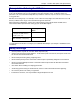
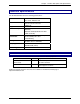
Chapter 1: Product Description and Specifications Technical Specifications The CF220 CallFinder meets the following specifications: Connectors 2 - RJ11-FXO/FXS Jacks, 2 - RJ12-DID line, RJ45 - Ethernet Jack Size 6”w, 1. 5”h, 9”d 15.2 cm x 3.8 cm x 22.9 cm Weight 0.90Kg 2lb Power Consumption Typical 8.8W (0.80A @5v DC + 0.10A @48vDC) Maximum 23.8W (0.88A @5.25v DC + 0.
Chapter 2: Sample System Chapter 2 – Sample System Introduction The Spigglebrim Vacuum Cleaner Company wants to use DID lines for its Field Support and Purchasing Departments. Alas, the company’s PBX is not equipped for DID service and a new PBX will not be in the budget anytime soon. This chapter shows how this fictitious company might use MultiTech’s CF220 CallFinder to solve its problem.
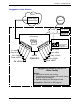
Chapter 2: Sample System Spigglebrim’s Initial Situation PSTN Local Telco Central Office Internet LAN Name Server 192.168.4.251 Mail Server mail.spigb.com Directory Number Range: 612-555-5xxx PBX [ ] No DID support. Phone/Computer Administrator Tom, x5001; tomq@spigb.com Eve, x5176 Al, x5203 Bea, x5119 Cal, x5857 Dora, x5071 Ed, x5486 Dan, x5890 x5000 Cindy, x 5549 Operator Bob, x5528 Ann, x5411 Spigglebrim Vacuum Cleaner Co. Office Facility Needs: 1. Automated, flexible call routing.
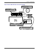
Chapter 2: Sample System Step 1 Practical: Add CallFinder and connect to network. CallFinder connects to Ethernet LAN. CallFinder is added. Internet Power 48Vdc Channel 2 FXS/FXO DID Channel 1 FXS/FXO DID Ethernet Power 5Vdc 10/100 LAN Name Server 192.168.4.251 Mail Server mail.spigb.com PBX [ ] No DID support. Phone/Computer Administrator CallFinder’s built-in software is accessed via web browser. CallFinder ties in with other servers on the network. Multi-Tech Systems, Inc.
Chapter 2: Sample System Step 1 Technical: Enter addresses of network servers in CF software. Once assigned an IP address on the network, the CallFinder’s software (configured via web browser) can link it to other servers on the network. CallFinder gets own IP address. Administration: Time Configuration Administration: IP Configuration IP Address 192.168.4.89 Subnet Mask 255.255.255.0 Name Server 192.168.4.251 time.nist.gov Time Server Add Time Server Default Gateway 192.168.4.
Chapter 2: Sample System Step 2 Practical: Add DID lines and connect to CallFinder. PSTN Local Telco Central Office Two DID lines (10 directory numbers each) are ordered from the telco. DID Lines Dir. Numbers: 3101-3110 Power 48Vdc Channel 2 3111-3110 Channel 1 FXS/FXO DID FXS/FXO DID Ethernet Power 5Vdc 10/100 PBX [ ] No DID support. Multi-Tech Systems, Inc.
Chapter 2: Sample System Step 2 Technical: Enter operating parameters of DID lines. Each DID line has 3 user-specified technical parameters. You set them in the CallFinder software.
Chapter 2: Sample System Step 3 Practical: Connect CallFinder port (FXO) to PBX for conventional DID service (Purchasing Dept.). DID Line from telco Dir. Numbers: 3111-3120 CF220 (Rear) CallFinder FXS/FXO Port (CH1) connects to a station port on the PBX. Power 48Vdc Channel 2 Channel 1 FXS/FXO DID FXS/FXO DID Trunk Port Ethernet Power 5Vdc 10/100 Station Port PBX [ ] No DID support. Eve, x5176 DID calls are treated like calls originating at other PBX extensions (”inside” calls).
Chapter 2: Sample System Step 3 Technical: Enter operating parameters of CallFinder channel (FXO) Each of the CallFinder’s DID-channel modems has 4 user-specified parameters. You set them in the CallFinder software.
Chapter 2: Sample System Step 4 Practical: Connect CallFinder port (FXS) to PBX for special DID service (Field Support Dept.). DID Line from telco Dir. Numbers: 3101-3110 CF220 (Rear) CallFinder FXS/FXO Port (CH2) connects to a trunk port on the PBX. Power 48Vdc Channel 2 Channel 1 FXS/FXO DID Ethernet FXS/FXO DID Trunk Port Power 5Vdc 10/100 Station Port PBX [ ] No DID support. DID calls are treated like calls originating outside of the PBX.
Chapter 2: Sample System Step 4 Technical: Enter operating parameters of CallFinder channel (FXS).
Chapter 2: Sample System Step 5 Practical: Map PBX Extensions to DID Numbers CF220 CallFinder Billing Computer FXS Port FXO Port Trunk Port Station Port CallFinder Administrator Phone/Computer Administrator Tom, x5001; tomq@spigb.com PBX Eve, x5176 Al, x5203 Bea, x5119 Cal, x5857 Dora, x5071 Ed, x5486 Multi-Tech Systems, Inc.
Chapter 2: Sample System Step 5 Technical: Create CallFinder Phonebook. This phonebook arrangement connects the five Field Support users to the CallFinder through one of the PBX’s trunk ports (using DID numbers 3101 through 3105). This facilitates the use of a billing computer for Field Support calls. The five Purchasing Department users are connected to the CallFinder through one of the PBX’s station ports (using DID number 3111 through 3115).
Chapter 2: Sample System Step 6: Administering the CallFinder System Multi-Tech CallFinder Call Router Model CF220 - Version 1.0 For initial Login, use: admin admin Username Password Then change Login later. Login Designate an administrator to receive call-logs via email. Administration: SMTP Configuration SMTP Server Address mail.spigb.com Administrator Email tomq.spigb.
Chapter 2: Sample System Conclusion The CallFinder solved Spigglebrim’s problem. It added DID functionality to their existing PBX. Al in the Field Support Department can now receive calls from the outside (dialed to 612-555-3101) while taking both internal and external calls using his 5203 PBX extension number. Al’s Field Support calls are handled as outside calls and they can be registered with a billing computer.
Chapter 3: CallFinder Server Installation Chapter 3 – CallFinder Server Installation This chapter shows you how to set up your Multi-Tech Model CF220 CallFinder. The setup process entails cabling the CF220 unit and configuring the CallFinder software. The CallFinder software resides on the CallFinder unit and does not need to be installed. Prerequisite: Ordering the DID Line To use the CallFinder system, you will need one or two DID (Direct Inward Dial) lines in your facility.
Chapter 3: CallFinder Server Installation You Supply • Two nearby AC power outlets • Two nearby connections to a PBX • A connection to your Ethernet LAN • One or two nearby analog DID trunk lines each with a block of associated DID telephone numbers • A PC with Ethernet connection and web browser from which to configure the CallFinder unit. (Windows or Linux can be used to access the CallFinder software.
Chapter 3: CallFinder Server Installation When connecting to a PBX Trunk Port, set the CallFinder channel to FXS. When the Channel Configuration | Extension Port software field has been set properly for both CallFinder channels, you can proceed to connect the cable between each of the CallFinder’s FXS/FXO ports and the corresponding PBX port. 4. Connect CallFinder to DID Lines Plug one end of the phone cable into the CallFinder’s Channel 1 DID jack and the other end into an analog DID trunk line jack.
Chapter 3: CallFinder Server Installation Part B: Configuring the CallFinder Server 1. Collecting Configuration Data The table below lists the information you will need to fill in on the various CallFinder Server screen. Gathering this information in advance will expedite the CallFinder configuration process.
Chapter 3: CallFinder Server Installation Ordinary User Parameters (for CallFinder Phonebook) Name Multi-Tech Systems, Inc.
Chapter 3: CallFinder Server Installation 2. Setting Admin PC to Startup IP Address a. Connect a pc to your network. b. Set the pc IP address to 192.168.2.x subnet (using any address excluding 192.168.2.1). Windows XP a. From the Windows desktop, right-click on “My Network Places,” and select “Properties.” b. In the Network Connection screen, right-click on “Local Area Connection.” c.
Chapter 3: CallFinder Server Installation 4. Setting CallFinder IP Addresses a. In the CallFinder Administration screen, go to the IP Configuration fields. Administration: IP Configuration IP Address 192.168.4.89 Subnet Mask 255.255.255.0 Name Server 192.168.11.251 Default Gateway 192.168.4.1 Secondary Name Server update b. Fill in the IP information that applies to your CF220 CallFinder Server unit. The fields for “IP Address,” “Subnet Mask,” “Default Gateway” and “Name Server” are required.
Chapter 3: CallFinder Server Installation 7. Setting Administrative Functions Go to the CallFinder Phone Book screen. a. Administrator Row: Specifying DID# and PBX Extension i. In the first row (marked Administrator) of the Phone Book screen, enter the DID number and PBX extension of the CallFinder administrator. The first row is always for the party who performs the ‘administrator’ function.
Chapter 3: CallFinder Server Installation 8. Setting Up the Mail Server The CallFinder uses a mail server to send, by email, call log reports to the administrator. An email is also sent to the administrator each time the CallFinder is powered up. In all cases, you must specify the address of the mail server and the email address of the administrator. Some email servers require authentication before allowing the CallFinder access.
Chapter 3: CallFinder Server Installation 9. Configuring the CallFinder’s Channels The CallFinder’s channels direct inbound calls to their proper destinations. a. In the CallFinder software, go to the Channel Configuration screen. b. Under Channel Configuration: Channel 1, enter the values that match the characteristics of your DID phone line in the fields provided. Three parameters relate to the DID line coming into the CallFinder channel.
Chapter 3: CallFinder Server Installation Extension Mic Gain: This value adjusts the volume of the phone’s microphone. Default = 8. Increase value if outgoing audio signal is constant but low. Decrease value if outgoing audio signal intermittently cuts out or is clipped. This parameter is sensitive and important to system performance. Extension Speaker Gain: This value adjusts the volume of the phone’s speaker. Default = 30. Increase value if outgoing audio signal is constant but low.
Chapter 3: CallFinder Server Installation 12. Changing Administrator’s Password for CallFinder SW a. In the Password Administration screen, enter a new User ID and Password for the CallFinder Administrator (something other than “admin” and “admin”). This User ID and password are used to give the administrator access to the CallFinder’s built-in software. Re-enter the password in the “Confirm Password” field. Passwords can be as short as 1 character, as long as 40 characters, and are case-sensitive. b.
Chapter 4: CallFinder Software Screens Chapter 4 – CallFinder Software Screens In this chapter, we present the screens of the CallFinder software. We describe each field in each screen and some of the command buttons. (We do not describe command buttons that have functions that would be readily understood by users of Windows software. Examples of such self-evident functions include buttons like “OK,” “Cancel,” “Next,” etc.
Chapter 4: CallFinder Software Screens Login Screen The CallFinder Server Login screen is the primary security device for the Server software. The CallFinder has a default setting that allows use of “admin” as both the User Name and the Password at initial startup. After you have begun configuring your CallFinder unit, you should change the password in the Password Administration screen described later in this chapter.
Chapter 4: CallFinder Software Screens Call Log Screen Call Log Screen Field Definitions Column Time Name Duration Multi-Tech Systems, Inc. Values mm/dd/yyyy + hh/mm/ss + am/pm dd/mm/yyyy + hh/mm/ss + am/pm yyyy/mm/dd + hh/mm/ss + am/pm alphanumeric mmm minutes ss seconds CF220 CallFinder User Guide Description Date and time at which call was received. Party receiving call. How long the call lasted.
Chapter 4: CallFinder Software Screens Current Status Screen Current Status Screen Field Definitions Field Name Values System fields group Current Time weekday, mo, dd hh:mm:ss yyyy Pending Msgs numeric Time Server Status Multi-Tech Systems, Inc. Initializing, No Errors, SNTP Error: type Description The present time of day. Emails that have arrived in the CallFinder unit that have not yet been conveyed to clients.
Chapter 4: CallFinder Software Screens Current Status Screen Field Definitions (cont’d) Field Name Values Description System fields group Up Time x days yy hours: Operation time since last reboot. zz minutes Email Status No Errors, Indicates whether or not the CallFinder can Bad MailServer communicate properly with an email server.
Chapter 4: CallFinder Software Screens Administration Screen Administration Screen Field Definitions Field Name Values Description IP Configuration Fields IP Address n.n.n.n for n = 0-255 The IP address of the CallFinder. Subnet Mask n.n.n.n for n = 0-255 This subnet mask is the subnet for the network to which the CallFinder is connected.
Chapter 4: CallFinder Software Screens Administration Screen Field Definitions Field Name Values Description SMTP Configuration Fields SMTP Server Address n.n.n.n for n = 0-255 Domain name or IP address for mail server (SMTP must be supported on mail server). Server User ID alphanumeric Identifier used by CallFinder when interfacing with mail server. CallFinder uses mail server to send call reports to administrator. Some email servers require authentication when accessed for this purpose.
Chapter 4: CallFinder Software Screens Administration Screen Field Definitions (continued) Field Name Values Description Time Configuration Fields (continued) Request Interval This value (to be set by user) indicates how often the CallFinder will update its clock from the Time Server. Update (button) Click on this button to make changes to Time Configuration settings take effect.
Chapter 4: CallFinder Software Screens Phone Book Screen The Phone Book screen maps the PBX extension phone numbers of clients to their respective external DID numbers. Phone Book Screen Field Definitions Field Name Values Name column alphanumeric DID Number column alphanumeric Extension column numeric Function column Buttons for Update, Delete, and Add functions Multi-Tech Systems, Inc. Description For each client entry, this column shows the client’s name.
Chapter 4: CallFinder Software Screens Phone Book Screen Field Definitions (cont’d) Field Name Values First row alphanumeric Second row (with default label “Unassigned Number”) alphanumeric Multi-Tech Systems, Inc. Description Administrator row. NOTE: This first row can be renamed as desired. However, its function will always remain the same: it is the party who serves as administrator for the CallFinder system. Do not enter the Name and DID number of an ordinary user in this field.
Chapter 4: CallFinder Software Screens Channel Configuration Screen “Channel Configuration: Channel 1 & Channel 2” Screen Field Definitions Field Name Values Max DID Digits 1-7 Extension Port FXS or FXO Extension Mic Gain Polarity DID Start 0 to 255 A or B wink, immediate, delay dial Description The number of digits that the telco supplies to the DID line when an incoming call is received. Default = 4. Denotes the interface type of the port (Channel 1 or Channel 2).
Chapter 4: CallFinder Software Screens “Channel Configuration: Channel 1 & Channel 2” Screen Field Definitions (cont’d) Field Name Auto Attendant Delay Values n= 0, n= 1-255 in seconds Description The CallFinder receives calls on the DID line and then passes them on to the PBX. Some PBXs have an auto-attendant for directing calls to PBX extensions. When the CallFinder directs an incoming call to the PBX it must sometimes wait some duration for a PBX auto-attendant before dialing the extension.
Chapter 4: CallFinder Software Screens Password Administration Screen The CallFinder software admits only one user, the administrator. As shipped, the administrator’s Username (User ID) is “admin” and the administrator’s password is also “admin.” You can use the Password Administration screen to change the administrative password parameters. “Password Administration” Screen Field Definitions Field Name Name User ID Password Confirm Password Function Multi-Tech Systems, Inc.
Chapter 4: CallFinder Server Operation Chapter 5 – CallFinder Server Operation Front Panel LEDs Label Name Identifier General LEDs Power Status TD RD TR DID TD RD TR DID ACT Line 1 LED Transmit Data Receive Data Terminal Ready DID Line 2 LEDs Transmit Data Receive Data Terminal Ready DID Ethernet LEDs Activity LINK Data Link SPEED Data Rate Description On if unit is on. Flashing Green = unit is functioning properly Solid Red = unit is having its software updated.
Chapter 4: CallFinder Server Operation Call Log Email Messages The CallFinder keeps track of the calls it handles. In a call log file, the CallFinder records who called, when, for how long, which DID number the call came in on, and which extension the call was completed to. The CallFinder sends the call log file to the administrator as an email attachment. Initializing and Busying DID Channel Modems The state of each DID channel modem is indicated in the Current Status screen.
Chapter 6: FFCF Manager Installation Chapter 6 - FFCF Manager Installation Introduction The FaxFinder/CallFinder Manager software is a separate program that allows you to control and configure multiple CallFinder units in one place. The program is shipped with the CallFinder unit and must be installed on a PC connected to the same Ethernet network as all CallFinder units that it controls.
Chapter 6: FFCF Manager Installation Installing FFCF Manager Software The process of installing the FFCF software is explained in the illustration below. Multi-Tech Systems, Inc.
Chapter 6: FFCF Manager Installation Uninstalling or Reinstalling the FFCF Manager Software 1. Go to Start | Settings | Control Panel | Add or Remove Programs. (The menu director location of the ‘Add/Remove Programs’ function varies for different types of Windows operating systems.) 2. Select the FaxFinder CallFinder Manager program and click Remove. Multi-Tech Systems, Inc.
Chapter 6: FFCF Manager Installation 3. A transient screen will appear while the ‘wizard’ program prepares to un-install the software. 4. At the ‘Welcome’ screen, select “Remove” to uninstall the FFCF Manager software or select “Repair” (or “Modify”) as needed to re-install or alter the existing installation of the software. Then click Next. Multi-Tech Systems, Inc.
Chapter 6: FFCF Manager Installation 5. At the next screen, confirm your decision to uninstall the FFCF Manager software by clicking Yes. 6. A transient screen appears while files are being removed. Multi-Tech Systems, Inc.
Chapter 6: FFCF Manager Installation 7. At the ‘completion’ screen, click Finish. Multi-Tech Systems, Inc.
Chapter 7: FFCF Manager Operation Chapter 7 - FFCF Manager Operation Introduction The commands of the FFCF Manager software are accessible in the program’s pulldown Edit menu, and through a right-click menu that becomes available when a particular CallFinder is selected in the program’s main screen. FFCF Manager Command Summary How to Access Command Command Name Summary Synchronize Phonebooks Copies main phonebook into other CallFinder units.
Chapter 7: FFCF Manager Operation Opening the FFCF Manager Software 1. To launch the FFCF Manager program from the Windows desktop, go to Start | Programs | FaxFinder/CallFinder Manager | FaxFinder/CallFinder Manager. 2. The FFCF Manager main screen will appear. Multi-Tech Systems, Inc.
Chapter 7: FFCF Manager Operation FFCF Manager Main Screen The FFCF Manager’s main screen lists the CallFinder units that are working together as a system. The system generally can consist of one CallFinder functioning as a master or server unit (designated as Primary) and one or more CallFinders functioning as client or slave units (designated as Copy). CallFinder units functioning without reliance on a server unit (designated as Independent) can also be part of the system.
Chapter 7: FFCF Manager Operation Main Screen Menu or Column Description File menu Contains the Exit command which closes the FFCF Manager program. Edit menu Allows you to add a CallFinder unit to the system and synchronize phonebooks from Primary CallFinder units to Copy CallFinder units within the system. Help menu Online help is not currently supported. See manuals.
Chapter 7: FFCF Manager Operation FFCF Manager “Edit” Menu Edit Menu Command Description Synchronize Phonebooks Transfers phonebook data from a Primary CallFinder unit to all CallFinders designated as Copy units. The phonebook sharing statuses of the CallFinders (Primary, Copy, or Independent) involved must be set in advance. That is, one CallFinder must be set as the Primary unit.
Chapter 7: FFCF Manager Operation Synchronizing Phonebooks When CallFinder phonebooks are synchronized, all non-administrative listings match. One CallFinder unit (the Primary unit) holds the master list that is transmitted (using the Synchronize Phonebooks command) to other CallFinder units in the system (Copy units). CallFinder units can operate in same system but have independent phonebooks, in which case they are designated Independent. Synchronizing phonebooks entails three steps: 1.
Chapter 7: FFCF Manager Operation 3. Invoking synchronization. In the main FFCF Manager screen, open the Edit menu and select Synchronize Phonebooks. The Synchronize Phone Books screen will appear along with a series of transient screens (denoting tftp data transfers) and confirmation screens (where you click OK to proceed).
Chapter 7: FFCF Manager Operation Adding CallFinders Any CallFinder unit to be added to the system and come under the management of the FFCF Manager software must be connected to the same IP network as the computer running the FFCF Manager software. To add a CallFinder to the system, start at the main FFCF Manager screen. Open the Edit menu and select Add FaxFinder/CallFinder.
Chapter 7: FFCF Manager Operation Right-Click Menu for Selected CallFinder Device Right-Click Menu Command Description Delete Dis-associates the selected CallFinder unit from the system of CallFinders listed in the FFCF software Device column. Save Configuration Saves the settings of the CallFinder’s builtin software, including the phonebook, on the PC on which the FFCF Manager software is running.
Chapter 7: FFCF Manager Operation Deleting a CallFinder Invoking the Delete command removes the selected CallFinder unit from the system. Once deleted, the CallFinder unit will no longer be under the management of the FFCF Manager software. Click Yes at the ‘confirmation’ screen to complete the deletion command. Multi-Tech Systems, Inc.
Chapter 7: FFCF Manager Operation Saving a Configuration The CallFinder saves all of its settings (IP address, password, DID channel modem parameters, phone book, etc.) internally. This group of settings is its configuration. This same group of settings can be saved on the computer running the FFCF Manager software. Once saved, the configuration can be retrieved from the computer and re-installed onto the CallFinder unit using the Restore Configuration command.
Chapter 7: FFCF Manager Operation Restoring a Configuration To re-install on the CallFinder unit a group of settings (configuration) previously saved on the computer running the FFCF Manager software, use the Restore Configuration command. FFCF Manager will browse, by default, to an automatically determined directory that contains a saved configuration. Multi-Tech Systems, Inc.
Chapter 7: FFCF Manager Operation Updating Firmware When Update command is invoked, the Update CallFinder N.N.N.N screen appears. From this screen you specify which device (server or DID channel modem) to update with which firmware file. From this screen, you can also identify the firmware versions currently installed and initiate the update process. Update CallFinder N.N.N.N Field Description Status Identifies the current condition of the CallFinder or the current process underway.
Chapter 7: FFCF Manager Operation Setting Phone Book Sharing The phonebook of a Primary CallFinder unit is a source or central phonebook. Phone numbers should be entered into this phonebook. The central phonebook list is downloaded (by use of Synchronize Phonebooks command) from the Primary CallFinder unit into the phonebook of each Copy CallFinder unit. If phone numbers are added to the phonebook of a Copy CallFinder phonebook, they will be overwritten and lost at the next Synchronize Phonebooks command.
Chapter 7: FFCF Manager Operation Firmware Updating Process - Detailed Over time, new versions of CallFinder firmware will be issued. When these newer versions become available, you will want to secure the firmware files (typically by downloading them from the MultiTech web site) and install them in the CallFinder. There are three parts to a full firmware update: (a) updating DID Channel1/Modem firmware (with file name of the form gpqg.
Chapter 7: FFCF Manager Operation 2. The Update CallFinder N.N.N.N screen will appear. The current firmware versions for the CallFinder’s DID modems, Channel 1 and Channel 2, will be listed in the main window. In the bottom (and largest) pane of the Update CallFinder n.n.n.n window, read the list and write down the version of firmware currently in use for the two DID-channel modems. Compare these versions with the update file that you plan to use.
Chapter 7: FFCF Manager Operation 3. Browse to the location of the most recent firmware file. 4. Click Start Update. 5. The CallFinder – Confirm Update screen will appear. Click OK. Multi-Tech Systems, Inc.
Chapter 7: FFCF Manager Operation 6. The updating process will take as long as a minute. During this time, several messages will appear in the Update CallFinder N.N.N.N window. A transient TFTP screen may appear briefly. If the updating process has been successful, the final message line will say “Finished – The FaxFinder/CallFinder is ready.” 7. Repeat steps 1-6 for the second channel of this CallFinder unit. For consistency of operation, update both channels of all CallFinder units in the system. 8.
Chapter 7: FFCF Manager Operation CallFinder Server Firmware Update 1. Bring up the FaxFinder/CallFinder Manager software main screen. In the Device column, identify the CallFinder unit on which the update is to be done. Be sure that the Status of that CallFinder unit is idle before continuing. (You cannot update the CallFinder while it is handling a call.) Select that CallFinder unit and right-click on it. In the menu that appears, select Update. 2. The Update CallFinder N.N.N.N screen will appear.
Chapter 7: FFCF Manager Operation In the bottom (and largest) pane of the Update CallFinder N.N.N.N window, read the list and write down the version of firmware currently in use for the CallFinder server and its two DIDchannel modems. Compare these versions with the update files that you plan to use. Make sure that the files to be installed really do supersede the ones currently installed on the CallFinder. In the CallFinder Update Select field, select “CallFinder firmware.” 3.
Chapter 7: FFCF Manager Operation 6. The updating process will take as long as a minute. During this time, several messages will appear in the Update CallFinder N.N.N.N window. A transient TFTP screen may appear briefly. If the updating process has been successful, the final message line will say “Finished – The FaxFinder/CallFinder is ready.” 7. Close the Update CallFinder N.N.N.N window. In the main FFCF Manager window, the updated version will be listed. Multi-Tech Systems, Inc.
Chapter 7: FFCF Manager Operation 8. Repeat steps 1-7 for each CallFinder unit in the system. NOTE: For proper operation of the CallFinder system, including the sharing of Phone Book data, the server firmware version for all CallFinder units must be the same. 9. The updating process is now complete. Click the “X” in the upper-right corner to return to the main FFCF Manager screen. Multi-Tech Systems, Inc.
Chapter 8: Troubleshooting Chapter 8: Troubleshooting 1. What if I can't see the web page for my CallFinder ? REMEDY: Is the status LED on the CallFinder unit blinking? If not, then the unit is either malfunctioning or not turned on. If the Status LED is blinking, then verify that the Admin PC is actually on the same subnet as the CallFinder and that the CallFinder can be “pinged.” Launch a Command Prompt. (In WinNT, go to Start | Programs | Command Prompt.
Chapter 8: Troubleshooting No email message after mail server setup (cont’d) If the mail server can be pinged neither by its domain name nor by its IP address, then consider item B below. CAUSE B: The mail server is not running or cannot be contacted from the CallFinder unit. RESPONSE B: Verify that the mail server is running by sending an email to yourself using your email software.
Chapter 8: Troubleshooting 3. What if the CallFinder channel doesn't answer a call on the DID line? REMEDY. Use this procedure if Channel Configuration cannot be confirmed (that is, if during a test call to one of the system's DID phone numbers, you fail to see the "Waiting for Connect" State in the Current Status: Channel-1/Channel-2 screen and if you fail to hear voice-- both the state and the sound must be observable). A.
Chapter 9: Regulatory Information Chapter 9 – Regulatory Information 47 CFR Part 68 Telecom 1. This equipment complies with Part 68 of the 47 CFR rules and the requirements adopted by the ACTA. Located on this equipment is a label that contains, among other information, the registration number and ringer equivalence number (REN) for this equipment or a product identifier in the format: For current products is US:AAAEQ##Txxxx. For legacy products is AU7USA-xxxxx-xx-x.
Chapter 9: Regulatory Information 12. Manufacturing Information: Manufacturer: Multi-Tech Systems, Inc. Trade Name: CallFinder Model Number: CF220 Registration No: US: AU7OTNANCF220 Ringer Equivalence: 0.4B Modular Jack (USOC): RJ11C or RJ11W (single line), RJ12 Service Center in USA: Multi-Tech Systems, Inc. 2205 Woodale Drive Mounds View, MN 55112 U.S.A.
Chapter 9: Regulatory Information Canadian Limitations Notice Notice: The ringer equivalence number (REN) assigned to each terminal device provides an indication of the maximum number of terminals allowed to be connected to a telephone interface. The termination on an interface may consist of any combination of devices subject only to the requirement that the sum of the ringer equivalence numbers of all the devices does not exceed 5. Notice: The Industry Canada label identifies certified equipment.
Chapter 10: Warranty, Service, & Repair Chapter 10: Warranty, Service, & Repair Multi-Tech Warranty Statement Multi-Tech Systems, Inc., (hereafter “MTS”) warrants that its products will be free from defects in material or workmanship for a period of two, five, or ten years (depending on model) from date of purchase, or if proof of purchase is not provided, two, five, or ten years (depending on model) from date of shipment.
Chapter 10: Warranty, Service, & Repair In the event that factory service is required, products may be shipped, freight prepaid to our Mounds View, Minnesota factory. Recommended international shipment methods are via Federal Express, UPS or DHL courier services, or by airmail parcel post; shipments made by any other method will be refused. A Returned Materials Authorization (RMA) is required for products shipped from outside the U.S.A. and Canada.