BA-Series Intelligent Data/Fax Modem User Guide
User Guide 88312001 Revision B MultiModemII Models: MT2834BA/MT2834BAI This publication may not be reproduced, in whole or in part, without prior expressed written permission from Multi-Tech Systems, Inc. All rights reserved. Copyright 1999-2002 ©, by Multi-Tech Systems, Inc. Multi-Tech Systems, Inc. makes no representations or warranties with respect to the contents hereof and specifically disclaims any implied warranties of merchantability or fitness for any particular purpose.
Contents Chapter 1 - Introduction and Description ......................................................................... 5 1.1 1.2 1.3 1.4 1.5 1.6 1.7 1.8 Introduction ...................................................................................................................................... How To Use This Manual ................................................................................................................. Modem Features .....................................................
Chapter 5 - S-Registers .................................................................................................... 49 5.1 5.2 Introduction ...................................................................................................................................... 50 Reading and Assigning S-Register Values ...................................................................................... 55 5.2.1 Examples of Assigning Values ...........................................................
Chapter 1 - Introduction and Description
MultiModemBA User Guide 1.1 Introduction Welcome to the world of data communications. You have acquired one of the finest intelligent desktop data/fax modems available today, the MultiModemII BA series modem, from Multi-Tech Systems. This User Guide covers various models within the BA series, and unless otherwise noted, all content should be considered relevant to all models. Your MultiModem provides data communication at the following rates: 33,600 - 14,400 bps (Enhanced V.34 / V.
Chapter 1 - Introduction and Description Chapter 6 - Callback and Remote Configuration Chapter 6 documents instructions on how to operate the modem's Callback and Remote Configuration features; and the usage of LOGIN Passwords, Set-Up Passwords and Remote Escape Characters as network management tools. Chapter 7 - DIP-Switches Chapter 7 covers the modem’s printed-circuit board options.
MultiModemBA User Guide 1.3.1 2834 Series Features Your MT2834BA modem meets the proposed Enhanced V.34 ITU standard for data signalling rates as high as 33.6/31.2K bps in full duplex mode. Enhanced V.34 is an extension of V.32/V.32bis/V34 standards, and supports and is compatible with those features, including EIA extended Automode; adaptive line probing; automatic symbol rate and carrier frequency during start-up; and retrain and rate renegotiation (in 2400 bps increments). The MT2834BA features ITU V.
Chapter 1 - Introduction and Description 1.
MultiModemBA User Guide 1.6 Fax Modulations V.21CH2 FSK at 300 bps, V.27ter DPSK at 4800 and 2400 bps, V.29 QAM at 9600 and 7200 bps, V.17 TCM at 14400, 12000, 9600, and 7200 bps Transmit Level -11dBm (dial-up), -9 or -15 dBm (leased-line); dBm level selectable with DIP-Switch #3 in leased line setting Frequency Stability ±0.01% Connectors One DB-25 RS-232C connector; two RJ11 for phone line/telephone set; power.
Chapter 1 - Introduction and Description 1.7 Modem LED Indicators The MultiModem diagnostic LED indicators are shown in Figures 1-1 SD RD CD 28.8 Send Rcv Carr 28.8K 24.0K 19.2K 14.4K 9600 2400 Off Hk Rdy 24.0 19.2 14.4 96 24 OH TR EC FX V.42 Fax MT2834BA Series Intelligent Modem Answ Orig Voice/ Data Figure 1-1. MT2834 LED Display (SD) Send (Transmit) Data. This LED blinks when data is being transmitted, on for a space, off for a mark.
MultiModemBA User Guide 1.8 Controls on PC Board The MultiModem is designed on a single printed circuit (PC) board. This board contains one 16position DIP-Switch (numbered 1-16). The DIP-Switches are accessible through a cut-out on the side of the modem. There is also a knob which is used to adjust the speaker volume. This knob is accessible through the modem's rear panel. The sixteen DIP-Switches control various modem options or set default values for Command Mode operation.
Chapter 2 - Installation and Connection
MultiModemBA User Guide 2.1 What is in Your Modem Package? Your MultiModem is made up of many components. Make sure you have them all before trying to operate your modem. MADE IN U. S.A SD RD CD 28.8 Send Rcv Carr 28.8K 24.0K 19.2K 14.4K 9600 2400 Off Hk Rdy 24.0 19.2 14.4 96 24 OH MADE IN TR EC FX V.42 Fax MT2834BA Series Intelligent Modem Answ Orig Voice/ Data U.S.A Figure 2-1.
Chapter 2 - Installation and Connection 2.2.1 Safety Warnings 1. Use this product only with UL and cUL listed computers. 2. To reduce the risk of fire, use only 26 AWG (.41mm) or larger telephone wiring. 3. Never install telephone wiring during a lightning storm. 4. Never install a telephone jack in wet locations unless the jack is specifically designed for wet locations. 5.
MultiModemBA User Guide 3 Connect the modem to a dial-up line by attaching the RJ-11 telephone cord (provided with your unit) to the LINE connector on the modem and to a dial-up wall jack. Refer to Figure 2-2. PHONE EIA RS232C LINE VOLUME ON OFF POWER Figure 2-2. MultiModemBA/BAI Connections 4 Attach the EIA RS-232C connector on the modem to the serial port on your computer or terminal with an RS-232 (or V.24) cable (you supply). Refer to Figure 2-2.
Chapter 3 - Software Configuration and Modem Basics
MultiModemBA User Guide 3.1 Introduction Chapter 2 described the installation of PhoneTools, a communications software. If you are using a different software package, there are some points you should take into consideration. Since your communications software configuration is affected by the capabilities of your computer, this chapter begins with a discussion of the limitations of some serial ports and how to identify them.
Chapter 3 - Software Configuration 3.4.1 Changing Default Parameters By default, the modem will answer after the first ring and try to communicate with a modem on the other end of the line. If you have one telephone line for voice, fax, and modem communications, the modem may attempt to answer all incoming calls, voice as well as data.
MultiModemBA User Guide 3.5.2 Terminal Emulation If you are accessing the remote computer as if from an on-site terminal, the keyboard codes used by your computer may not match the ones used by the remote computer. To be compatible with the remote computer, your software must be able to substitute the appropriate codes in what is known as terminal emulation.
Chapter 4 - Command Mode
MultiModemBA User Guide 4.1 Introduction AT commands are the means by which you, and your communications software, are able to communicate with and configure your modem. They enable you to establish, read, and modify parameters in addition to dialing. The following provides both a summary and a detailed explanation of the AT commands recognized by the MultiModem. 4.1.1 AT Command Editing The BACKSPACE key on your keyboard can be used to edit characters in the AT command line.
Chapter 4 - Command Mode COMMAND MODE HANG UP +++AT Dial (D or A) command, or incoming phone call WAIT FOR CARRIER No carrier detected Carrier detected ON-LINE MODE Carrier lost AT0 Command Figure 41. Functional Modes 4.2 Summary of AT Commands A wide variety of autodial operations and modem options can be controlled when the modem is in Command Mode. Remember, nearly all commands begin with AT. These commands are organized into several functional groups.
MultiModemBA User Guide STORE MODEM CONFIGURATIONS AND DEFAULTS 24 &F &W Z V $SP &M &X Load Factory Defaults Store Configuration & S-Register Parameters Reset Modem Result Code Terse/Verbose UNIX/"Spoofing” Synchronous/Asynchronous Mode Select Synchronous Transmit Clock Select CONFIGURE COMMAND RESPONSES Q &Q E V X Result Codes Enable/Disable Response Result Code Selection Echo Command Characters Result Code Terse/Verbose Result Code...
Chapter 4 - Command Mode CONFIGURE DATA COMPRESSION &E14 &E15 Data Compression Disabled Data Compression Enabled CONFIGURE SPEED CONVERSION $BA0 $BA1 $MB $SB Speed Conversion On Speed Conversion Off Set modem speed (e.g.,$MB14400) Set serial port speed (e.g.
MultiModemBA User Guide 4.3 Result Codes The Command mode provides you with several responses, or “Result Codes”, that can aid you in Command mode operation. These Result Codes are displayed on your video monitor. You can choose result codes that closely match those of the standard AT command set, or choose enhanced function result codes that have been used in Multi-Tech modems ("Multi-Tech" responses). The &Q command selects which result codes will be used.
Chapter 4 - Command Mode 4.4 Dialing Commands 4.4.1 Dialing Action Commands Dial Command D The letter D in a command causes the modem to dial the telephone number immediately following it. For example, if you enter ATD5551212 and hit RETURN, the modem dials the number 555-1212. The D command is also used in conjunction with a telephone set for manual dialing. You dial the number on your telephone set, and after hearing the answer tone on your handset, you type ATD on your keyboard and hit RETURN.
MultiModemBA User Guide DTR Dialing $D An alternate method of causing the modem to automatically dial is DTR Dialing. Data Terminal Ready (DTR) is a signal that comes into the modem from the terminal or computer to which it is connected, on pin 20 of the RS-232C interface. In DTR dialing, the modem automatically dials a stored number as soon as it receives a high DTR Signal. The DTR dialing method is popular in synchronous applications. To activate DTR Dialing, enter AT$D1 and hit RETURN.
Chapter 4 - Command Mode Set Pulse Dial Ratios &P This command sets the time ratios between the open and closed portions of the dialing pulse frequencies. To set the dialing pulse ratio of 60 mSec to 40 mSec, enter AT&P0. To set a ratio of 67 mSec to 33 mSec, enter AT&P1. The factory default is &P0. Automatic Pauses in Dialing , You can cause the modem to pause during the dialing sequence by entering a comma character where the pause is desired. This pause lasts two seconds.
MultiModemBA User Guide Flash On Hook ! Some switchboard systems react to a momentary On Hook. An exclamation mark inserted in the command causes the modem to “flash” on hook for a half of a second, as if you had held the switch hook button on a telephone down for a half second. For example, to flash On Hook after dialing the number 555-1234 in order to transfer to Extension #5678, you might enter ATDT5551234,,!5678. The commas cause a 4 second pause (just to be safe).
Chapter 4 - Command Mode Number Linking NN You may command the modem to dial another number automatically if the first number dialed is busy. This would be useful in a situation where a computer can be accessed through more than one phone number. This is called “linking”. To link the number in N1 to the number N2, simply enter ATN1N2 and hit RETURN. Several numbers can be linked in the same command.
MultiModemBA User Guide Loading Factory Defaults &F The &F command provides a choice between customized configuration settings in RAM and the factory default configuration settings in ROM. The &F8 and &F9 commands define the function of the &F command. The modem is shipped from the factory with a pre-configured set of command and S-Register default settings. This set of factory defaults can be recalled by issuing the &F command.
Chapter 4 - Command Mode &X0 is the default setting, which allows DIP-Switch #11 to control Internal/External Clocking (default Internal). Internal clocking is when the modem provides transmit clock to the DTE on pin 15 of the RS-232C/V.24 interface. The &X1 command overrides DIP-Switch #11 and selects External clocking. If DIP-Switch #11 is UP (External clocking), you can not override Internal clocking. &X2 enables Slave Clocking.
MultiModemBA User Guide Result Codes (Basic and Extended) and Call Progress Selection X The X Command is used to select one of two possible dialing methods (“dumb” or “smart”), and to select various response combinations related to these methods. You can choose to have certain responses suppressed, or whether or not you want speed indications along with the CONNECT responses. You can also pick and choose certain responses in order to match up with “Standard AT” responses.
Chapter 4 - Command Mode Bell/V.21 Tone B The B command selects the frequency that the modem uses for its answer tone. (The answer tone is the tone transmitted by a modem receiving a call to the modem that called it, which initiates the handshaking between the two modems.) At higher speeds there is no conflict, because all use CCITT frequencies. At lower speeds (0-1200 bps), in the U.S., some modems use the Bell frequency of 2225 Hz. However, the CCITT specification for V.
MultiModemBA User Guide Enable/Disable Lowspeed Fast Connect $FC Entering AT$FC0&W0 sets up the data pump so that it will not transmit a 5 second 2100 Hz signal. Entering AT$FC0&W0 allows the modem to transmit a 5 second 2100 Hz signal and is the factory default. Cleardown at Disconnect &CD The &CD command is used for control of cleardown at disconnect in V.32, V.32bis, V.34 and V.34 enhanced modes.
Chapter 4 - Command Mode Data Terminal Ready Control &D Data Terminal Ready (DTR) on pin 20 of the RS-232C interface is required in order for the modem to operate. A high DTR signal tells the modem that the device to which it is connected is active, or "ready" to communicate through the modem. If the signal is not being provided on the RS-232C interface, you can force DTR high with DIP-Switch #1. DTR has some other modem functions. DTR can be used to trigger a dialing sequence, called DTR Dialing.
MultiModemBA User Guide DSR/CD Interaction Control &SF In typical applications, Data Set Ready (DSR) follows Carrier Detect (CD). &SF0 enables DSR to follow CD, and is the factory default. &SF1 enables DSR to operate independent of CD. If this is your application, refer to the &S command for control of the Data Set Ready signal. 4.4.8 Error Correction Commands You can use AT commands to place your modem one of three V.42 (error correction) modes of operation.
Chapter 4 - Command Mode #L0 Command The #L0 Command allows a pair of modems to negotiate which V.42 mode (MNP or LAP-M) will be used in their transmissions. Originate Mode a. If both modems have LAP-M capability, the modems use LAP-M mode. b. If one or both modems do not have LAP-M capability and both have MNP, the modems use the MNP mode. Answer Mode a.
MultiModemBA User Guide Retransmit Count $R If errors are received during a Reliable connection, the modem re-sends the block of data which contained an error. With the $R0 command, if another error occurs, the block will be re-sent again. The modem counts the number of times that a data block is re-sent. If the same block of data is resent 12 times and still has not been received properly, the modem assumes that the transmission line is unsuitable for transmission, and abort the connection.
Chapter 4 - Command Mode Hardware Flow Control &E4 With Hardware Flow Control, the modem uses its RS-232C interface to control the flow of data from the computer or terminal to which it is attached. The CTS (Clear to Send) signal on Pin 5 of the RS232C interface is brought low to stop the flow of data, and is brought high to restart it. When you select Hardware Flow Control as your Modem Initiated Flow Control method, you will also be selecting it for Pacing.
MultiModemBA User Guide Send Xon/Xoff Characters #X The #X phone interface command allows the modem to send either a single or multiple Xoff characters at the modem's buffer full level. When the modem’s buffer reaches it's "buffer full" level, the next character received causes another Xoff to be sent for every character subsequently received by the modem. The AT#X0 command (factory default setting) causes one Xoff to be sent until the buffer reaches the Xon level.
Chapter 4 - Command Mode Parity Selection #P The #P command enables the setting of parity. AT#P0 selects no parity. AT#P1 selects odd parity. AT#P2 selects even parity and is the default value. Note when setting up your data comm software, it is critical that both your remote and local system's parity selection be set identically. AT#P0 = no parity AT#P1 = odd parity AT#P2 = even parity The factory default setting is AT#P2. 4.4.
MultiModemBA User Guide 4.4.11 Speed Conversion Commands Speed conversion is a necessary part of data compression since data must be presented to the modem faster than it can handle data, if data compression is to be effective. Speed conversion allows the modem to communicate at one speed over the phone line, and at another speed at the RS-232C interface.
Chapter 4 - Command Mode Serial Port Baud Rate $SB The $SB command presets the speed of the modem’s serial (RS-232C) port, in both Originate and Answer modes. Speed conversion allows you to set this serial port baud rate at a fixed speed of up to 115,200 bps for 1932 and 2834 models, and 57600 bps for 1432 models, regardless of the modem’s transmission speed setting. In order for this command to be effective, the modem’s Speed Conversion feature must first be turned off with the $BA command.
MultiModemBA User Guide 4.4.12 Immediate Action Commands Help Screens $H The Help command is designed to give you short explanations on how to use each modem command. The Help command can be quite useful if your manual is not handy and you are in the middle of a communications session. Although the explanations are quite abbreviated compared to those in this manual, they should prove to be helpful reminders when needed.
Chapter 4 - Command Mode Off Hook H You can make the modem hang up (go On Hook). Entering ATH1 brings the line Off Hook, just as if you picked up the telephone set. You can hang up by entering ATH0 or ATH (the default is 0 when no number is entered). Escape Sequences- Entering Command Mode While Still On-Line +++AT It is possible to cause the modem to enter Command mode after the modem has gone on-line with a remote modem, without disconnecting the call.
MultiModemBA User Guide Exiting Command Mode, Going Back On-Line O You can bring the modem out of Command mode and back into On-Line mode by entering ATO (where O is the letter O, not the number 0). In this case, the O command reverses what was done by entering the Escape Code. The O command will bring the modem into the same On-Line mode (Originate or Answer) that it was in prior to going into Command mode. 4.4.13 Line Probe Commands Before V.
Chapter 5 - S-Registers
MultiModemBA User Guide 5.1 Introduction Certain Command Mode configurations are stored in memory registers called, S-Registers. The S command is used to assign a value to, and to read the current value of an S-Register. To assign a value to an S-Register, enter the letter S, followed by the S-Register number and an equals sign (=), and then a decimal response to the message “ENTER THE NEW VALUE IN DECIMAL FORMAT”.
Chapter 5 - S-Registers S4 Line Feed Character Unit: Range: Default: Description: ASCII Character 0-127 10 (^J) S4 defines the character recognized as Line Feed. S3 may be set for any ASCII character. S5 Backspace Character Unit: Range: Default: Description: ASCII Character 0-127 8 (^H) S5 defines the character recognized as BACKSPACE. S5 may be set for any ASCII character.
MultiModemBA User Guide S9 Carrier Detect Response Time Unit: Range: Default: Description: 100 mSec. 1-255 6 S9 sets the time delay between when the modem first detects a valid incoming carrier signal and when the modem turns on its Carrier Detect circuit. The default setting is 600 milliseconds, or six units of 100 mSec each (Decimal 6). S9 may be set for up to 25.5 seconds. S10 Carrier Loss Disconnect Delay Time Unit: Range: Default: Description: 100 mSec.
Chapter 5 - S-Registers S15 Callback Time Delay Unit: Range: Default: Description: Seconds 10-255 20 S15 defines the time delay between Callback attempts after initial passwords have been exchanged between modems. S16 Callback Attempts Unit: Range: Default: Description: 1 Attempt 1-255 4 S16 defines the number of attempts allowed after initial passwords have been exchanged between modems. S17 Changing Break Time Unit: Range: Default: Description: 10 mSec. 0-2.
MultiModemBA User Guide S26 Failed Password Attempts Unit: Range: Default: Description: 1 failed attempt 0-255 0 S26 counts the number of times there has been a failed password attempt. For example, if you entered ATS26? the message 003 would be displayed, meaning someone has failed three times to gain access to your modem using its password security system.
Chapter 5 - S-Registers S36 Time Between DTR Inactive and Modem Off-Hook Unit: Range: Default: Description: 1 Second 0-255 seconds 0 The DTR Busy-out feature uses S-Register S36 to set the time between DTR inactive (low) and the modem going off-hook. S36 can be set in one-second intervals from 0 to 255 seconds. With the default setting of S36=0, DTR Busy-Out is disabled (i.e., DTR won't Busy-Out).
MultiModemBA User Guide 5.2.1 Examples of Assigning Values 1. Let’s say you wish to have longer pauses caused by the comma in a dial command; five seconds instead of two. Entering ATS8=5 assigns 5 as the value for S-Register S8 (meaning the modem pauses five seconds for a comma in a dial command). 2. In a second example, let’s say that you wish to configure the modem to answer incoming calls after the 30th ring instead of after the first ring.
Chapter 6 - Callback Security and Remote Configuration
MultiModemBA User Guide 6.1 Introduction This chapter describes how the MultiModem’s Callback and Remote Configuration features operate. These features use a multilevel security system, which involves the use of LOGIN Passwords, Setup Passwords and Remote Escape Characters. The primary level security code is the modem’s LOGIN Password. Once this password is entered, other passwords can be used.
Chapter 6 - Callback Security and Remote Configuration Table 6-1. Modem LOGIN, Setup and Remote Escape Code Procedures To change your modem’s LOGIN Password and Setup Password: Step Procedure Note: Passwords are upper/lower case sensitive. The case you enter here is the case that must be used at Log-In. 1. Type AT#IMULTI-TECH and hit RETURN. Your modem will respond with: OK (if the LOGIN Password is wrong, the modem’s response is ERROR) 2. Type AT#SMODEMSETUP and hit RETURN.
MultiModemBA User Guide Table 6-2. Callback Password and Dial Back Phone Number Entry Procedures Step Procedure 1. Enter your modem's LOGIN Password (as selected in Table 6-1) by entering the following: AT#Ixxxxxxxxxx (xxxxxxxxxx from Table 6-1) Enter your modem's Setup Password (as selected in Table 6-1) by entering the following: AT#Syyyyyyyyyy(yyyyyyyyyy from Table 6-1) 2.
Chapter 6 - Callback Security and Remote Configuration 7. Enter your modem's LOGIN Password (as selected in Table 6-1) by entering: AT#Ixxxxxxxxxx (xxxxxxxxxx from Table 6-1) 8. Enter your modem's Setup Password (as selected in Table 6-1) by entering: AT#Syyyyyyyyyy (yyyyyyyyyy from Table 6-1) Table 6-3. Callback Operational Sequence Procedures Perform the following steps when dialing into a dialback modem: Step Procedure 1.
MultiModemBA User Guide 2. You then select 1 or 2. With 1, the modem goes back into data mode and with 2, the modem responds with the following: Password> 3. Enter your Setup Password, and if the code is correct the modem responds with: OK You can now use any AT commands of the modem being remotely configured as if they were being entered locally. You cannot change the setup of the LOGIN Password until you enter the proper LOGIN Password. 4.
Chapter 6 - Callback Security and Remote Configuration Change SETUP Password #S The default SETUP password for your modem is "SMODEMSETUP". If you choose to activate callback security, you should change the SETUP password using this command in the following format: AT#Stttttttttt (where tttttttttt is the current SETUP password).
MultiModemBA User Guide Local Inactivity Timer (S29) S29 defines the amount of idle time that can elapse between AT commands after the SETUP password has been entered. If this timer expires, the LOGIN and SETUP passwords will have to be re-entered. S29 only takes effect when the modem has been sent a #DB1 command, which secures the modem from local and remote configuration or dialing (i.e., no AT commands can be sent until the LOGIN and SETUP passwords have been entered).
Chapter 7 - DIP-Switch Settings
MultiModemBA User Guide 7.1 Introduction There are several DIP-Switch options on the modem’s printed circuit (PC) board. The DIP-Switches are accessible through a cut-out on the side of the modem. This chapter explains the modem’s printed-circuit board options. Sixteen DIP-Switch settings and the modem's speaker volume control are explained in detail, including all default settings. Power Switch Power Jack LED Indicators RS-232/V.
Chapter 7 - DIP-Switch Settings Switch #2 SDLC/BSC Option (Synchronous Mode/Leased Line/Dial-Up) Synchronous Data Link Control (SDLC) and Binary Synchronous Control (BSC) are two error correction protocols used in the IBM Mainframe environment. Place DIP-Switch #2 in the UP position to enable SDLC mode, and place DIP-Switch #2 in the DOWN position to enable BSC mode.
MultiModemBA User Guide Switch #4 Unix UUCP Spoofing (Asynchronous Mode/Leased Line/Dial-Up) The modem can be configured for use with Unix equipment which employs ACK flow control to monitor data integrity. The modem can do "UUCP spoofing", where the modem is able to generate ACKs at the DTE interface. Data then is transmitted more time-efficiently, because the delay of waiting for data to be received then waiting for the ACK to be returned at the remote end, is eliminated.
Chapter 7 - DIP-Switch Settings Switch #6 Slave Clocking (Synchronous Mode/Leased Line/Dial-Up) In Synchronous mode, DIP-Switch #6 controls the option of having timing controlled by the receive clock. The originate modem, in effect, adjusts to the answer (remote) modem. Place DIP-Switch #6 in the DOWN position to enable Slave Clocking. Place DIP-Switch #6 in the UP position to disable Slave Clocking.
MultiModemBA User Guide Switch #10 Leased Line/Dial-Up Operation -- "DDD" (Asynchronous/Synchronous Mode/Leased Line/Dial-Up) The modem operates in either leased-line or dial-up modes. This switch controls leased-line/dial-up operation. Place DIP-Switch #10 in the UP position for Dial-Up operation.
Chapter 7 - DIP-Switch Settings Switches #13 and #14 Speed Switches (Synchronous Mode/Leased Line) DIP-Switches #13 and #14 are used to set the modem’s data transmission rate. Switches #13 and #14 are used in combination, typically in leased-line and call origination applications. Note: The modem baud rate command ($MBn) overrides the setting of these speed selection switches (DIP switches #13 and #14).
MultiModemBA User Guide 7.4 Recording Option Configurations This section lets you record any changes you may have made to the DIP-Switch settings. Circle the appropriate setting and record the effect for future reference.
Chapter 7 - DIP-Switch Settings DIP Switches #13-14 Note: The modem baud rate command ($MBn) overrides the setting of these speed selection switches (DIP switches #13 and #14). SWITCH CONDITION EFFECT #13/#14 UP/UP* 28.8 K bps Operation #13/#14 DOWN/UP 19.2 K bps Operation #13/#14 UP/DOWN 14.
Chapter 8 - Warranty, Service and Tech Support
Chapter 8 - Warranty, Service, and Technical Support 8.1 Introduction This chapter starts out with statements about your modem's 5-year warranty. The next section, Tech Support, should be read carefully if you have questions or problems with your modem. It includes the technical support telephone numbers, space for recording your modem information, and an explanation of how to send in your modem should you require service.
MultiModemBA User Guide Please direct your questions regarding technical matters, product configuration, verification that the product is defective, etc., to our Technical Support department at (800) 972-2439 or email tsupport@multitech.com. Please direct your questions regarding repair expediting, receiving, shipping, billing, etc., to our Repair Accounting department at (800) 328-9717 or (763) 717-5631, or email mtsrepair@multitech.com.
Chapter 8 - Warranty, Service, and Technical Support 8.4 Replacement Parts SupplyNet, Inc., can supply you with replacement power supplies, cables and connectors for selected Multi-Tech products. You can place an order with SupplyNet via mail, phone, fax or the Internet at the following addresses: Mail: SupplyNet, Inc. 614 Corporate Way Valley Cottage, NY 10989 Phone: 800 826-0279 Fax: 914 267-2420 Email: info@thesupplynet.com Internet: http://www.thesupplynet.com 8.
Appendixes
Appendix A - Upgrading Your Modem’s Firmware Appendix A -- Upgrading Your Modem’s Firmware Your modem is controlled by semi-permanent software, called firmware, which is stored in flash memory. Firmware is nonvolatile; that is, it remains stored in memory when the modem is turned off. However, it can be changed by either the manufacturer or the user as bugs are fixed or new features are added.
MultiModemBA User Guide 5. If the firmware version number is greater than the firmware version number found in “Step 1: Identify the Modem Firmware,” your modem has an older firmware version. Continue with “Step 3: Download the Upgrade File.” Warning: The first digit of the new firmware must match the first digit of the old firmware, or the modem may not work properly. E.g., if your current firmware version is 4.16, replace it only with 4.xx firmware, not 6.xx firmware.
Appendix A - Upgrading Your Modem’s Firmware Step 6: Upgrade the Modem’s Firmware Before you begin the following procedure, read the README.TXT file extracted from the upgrade archive file. Note the file name for the new firmware (example: ARQG125A.HEX). WARNING: Never install an older version of firmware over a newer version. Doing this WILL DESTROY THE FLASH PROM! If the flash PROM is destroyed, the modem must be sent in for repair. 1.
MultiModemBA User Guide Appendix B - Troubleshooting Your modem was thoroughly tested at the factory before it was shipped. If you are unable to make a successful connection or if you experience data loss or garbled characters during your connection, it is possible that the modem is defective. However, it is more likely that the source of your problem lies elsewhere. Problems you may encounter include the following: • • • • • • • • • None of the LEDs light when the modem is on.
Appendix B - Troubleshooting • If you don’t get an OK, the problem may still be in the communications software. Make sure you have done whatever is necessary in your software to make a port connection. Not all communications programs connect to the COM port automatically. Some connect when the software loads and remain connected until the program terminates. Others can disconnect without exiting the program (make sure the Connect icon looks plugged in).
MultiModemBA User Guide The Modem Dials But Cannot Make a Connection There can be several reasons the modem fails to make a connection. Possibilities include • • • • • • • lack of a physical connection to the telephone line. a wrong dial tone. a busy signal. a wrong number. no modem at the other end. a faulty modem, computer, or software at the other end. incompatibility between modems. You can narrow the list of possibilities by using extended result codes.
Appendix B - Troubleshooting The Modem Disconnects While On-line • If you have call waiting on the same phone line as your modem, it may interrupt your connection when someone tries to call you. If you have call waiting, disable it before each call. In most telephone areas, you can disable call waiting by preceding the telephone number with *70 (check with your local telephone company). You can automatically disable call waiting by including the disabling code in the modem’s dial prefix (e.g.
MultiModemBA User Guide I Am Getting Garbage Characters on the Monitor • Your computer and the remote computer may be set to different word lengths, stop bits, or parities. If you have connected at 8-N-1, try changing to 7-E-1, or vice-versa, using your communications software. • You may be experiencing line noise. Enable error correction, if it is disabled, or hang up and call again; you may get a better connection.
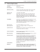
Appendix C - AT Command Summary Apendix C - AT Command Summary Command Values Description AT Attention Code that precedes most command strings except A/, A: and Escape Codes. RETURN Pressing RETURN key executes most commands. $ This symbol placed in dialing string enables the modem to detect AT&T's "call card" tones for accessing user's calling card to originate an on-line connection. A Answer call, even if no ring present. Repeat last command. (Do not precede this command with AT.
MultiModemBA User Guide Command Values Description DsNd s = phone # Store telephone number. To store, phone d = 0 thru 9 number ”s“ is entered and followed by N and then Directory Number “d.” &Dn n = 0 thru 3 &D0 DTR is ignored &D1 means modem returns to command mode. &D2 lets modem react to DTR normally. &D3 causes modem to reset to modem default parameters. * %DFn n = 0 or 1 * %DF0 Line Probe Data in Graph Format. %DF1 Line Probe Data in Table Format.
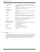
Appendix C - AT Command Summary &Fn n = 0, 8 or 9 * $Fn n = 0 or 1 * &F loads factory default values from ROM. &F8 reads factory default values and switch settings when &F is issued. &F9 reads parameters stored in non-volatile memory when &F is issued. $F0 means do not fall back to normal connect if CR received. $F1 means fall back to normal connect if CR received. &Gn n = 0, 1 or 2 Hn n = 0 or 1 H0 means Hang Up (go on hook). H1 means Go Off Hook. $Hn n = 1 thru 3 $H1 brings up Help Screen #1.
MultiModemBA User Guide $MBn n = speed * &Mn n = 0 or 1 Nd d = 0 thru 9 Dial stored telephone number “d” (Do not include the letter D in this command.) NdNe d = 0 thru 9 e = any other number 0 thru 9 Number Linking. If first number dialed is busy, another stored number may be automatically dialed. In example, stored number d is dialed, and if busy, stored number e is dialed. * O &M0 selects Async when on-line. &M1 selects Sync when on-line. Exit Command Mode and go into On-Line Mode.
Appendix C - AT Command Summary $SBn n = speed * &SFn n = 0 or 1 &Sn n = 0, 1 or 2 * * $SPn n = 0 or 1 * T &Tn n = 4 or 5 n = 0 or 1 * Un n = 0, 1, 2, or 3 $VDn n= 0 or 1 Vn n = 0 or 1 &S0 forces Data Set Ready On. &S1 lets Data Set Ready act normally. &S2 Data Set Ready drop is regulated by S24 on disconnect. $SP0 disables UUCP Spoofing $SP1 enables UUCP Spoofing &T4 means Enable Response to Request for Remote Digital Loopback.
MultiModemBA User Guide Xn n = 0,1,2,3 or 4 * X0 selects Basic Result Codes (w/o CONNECT 1200, CONNECT 2400). X1 selects Extended Result Codes (w/CONNECT 1200, CONNECT 2400). X2 selects Standard AT Command set with NO DIAL TONE. X3 selects Standard AT Command set with BUSY. X4 selects Standard AT Command set with NO DIAL TONE and BUSY. #Xn n= 0 or 1 * #X0 selects single XOFF character sent until XON level returns. #X1 selects multiple XOFF characters after buffer level is full.
Appendix C - AT Command Summary Callback Security/Remote Configuration Command Summary Command Description #DBn #DB0 disables Callback Security and answering Yes to the prompt turns off Callback Security and erases stored phone numbers and passwords. Answering No to the prompt aborts the command. #DB1 activates remote and local password security. #DB2 activates remote password security. #CBNyyxxxxxx Callback password with xxxxxx being callback password and yy being the memory location.
MultiModemBA User Guide Password Command Summary 94 Command Description #Ixxxxxxxxxx Login Password is any keyboard characters (x) (upper/lower case sensitive), minimum 6 and maximum 10 characters. The default Login Password is #IMULTI-TECH. #Syyyyyyyyyy Setup Password is any keyboard characters (y) (upper/lower case sensitive), minimum 6 and maximum 10 characters. The default Setup Password is #SMODEMSETUP.
Appendix C - AT Command Summary V.25bis Commands Command Description $Vn $V0 returns modem to AT command mode when in V.25bis mode. $V1 enables V.25bis mode of operation. $V2 allows modem to receive one V.25bis command while in AT command mode without leaving AT command mode. $V5 DSR follows DTR in V.25bis mode. $V6 DSR does not follow DTR in V.25bis mode. CSPs Changes the serial bps rate.
MultiModemBA User Guide Appendix D - V.25bis Operation Chapter 4 described a set of commands which let the modem dial, hang-up, and be configured for various applications. However, these commands, the AT command set, are only functional when the DTE transmits data asynchronously. That is, they cannot be used with synchronous equipment such as that found in IBM's Binary Synchronous Communications (BSC) and Synchronous Data Link Control (SDLC)* environments. The ITU V.
Appendix D - V.25bis Operation Another asynchronous mode concern is the problem of connecting at a different speed than the speed at which the serial port is set. If your modem port speed is different from the serial port speed, you must either: 1) Enable speed conversion and have flow control on, or 2) Enable connect responses (with the ATX1 command) and change the serial baud rate after receiving a connect message.
MultiModemBA User Guide V.25bis Responses (Result Codes) When in V.25bis mode (the AT$V1 command executed), your modem provides you with several responses which can help you follow the progress of V.25bis operations. These are similar to the Result Codes associated with AT Command mode operation. The V.25bis responses are in the form of three-character mnemonics as listed below: INC VAL DLCt CFlrr LSNmm;dd...dd LSDmm;dd...dd LSFmm;dd...dd CON ssss Incoming Call (same as RING indicator) A valid V.
Appendix D - V.25bis Operation Dial Phone Number Provided (CRN) Command The CRN command permits the dialing of the phone number immediately following it (from the command line). It is similar to the D command of the AT command set, except that the number is first checked against the Delayed Number and Forbidden Number list. If permitted, depending on the country regulations in effect, the number will then be dialed. For example, if you enter CRN7859875 and hit RETURN, your modem will check the two lists.
MultiModemBA User Guide DTR Dialing ($D) Command DTR Dialing is an alternate method of causing the modem to automatically dial a number. Data Terminal Ready (DTR) is a signal that comes into the modem from the terminal or computer to which it is connected via pin 20 of the RS-232 interface. In DTR Dialing, the modem will automatically dial a stored number as soon as it receives a high DTR signal. The DTR Dialing method is popular when using the modem in synchronous applications.
Appendix E - MultiModemBA Cables 3. Austria a) b) c) Command/Indication modification (none) Delayed and Forbidden list behavior 1. No delay between retries 2. After 2 retries to numbers that answer, but give no answer tone (CFINT), the number is put on the forbidden list 3. After 10 retries with busy or no dialtone, the number is put on the forbidden list 4. The number remains on the forbidden list forever 5. Delayed and Forbidden Numbers lists are checked when dialing in AT mode.
MultiModemBA User Guide Appendix E - MultiModemBA Cables These cables connect your modem to your terminal or computer’s serial port. 25-PIN DTE Connector TD 25-PIN DCE Device 2 2 TD RD 3 3 RD RTS 4 4 RTS CTS 5 5 CTS DSR 6 6 DSR GND 7 7 GND CD 8 8 DTR20 20 DTR RI 22 22 CD RI Figure E-1. RS232 Cable (IBM PC) 1 2 3 4 5 RED (Tip) GREEN (Ring) 6 RJ-11 Type Modular Plug To Terminal Block Screws (Transmit and Receive) Figure E-2.
Appendix F - Regulatory Information Appendix F - Regulatory Information FCC Part 15 This equipment has been tested and found to comply with the limits for a Class B digital device, pursuant to Part 15 of the FCC Rules. These limits are designed to provide reasonable protection against harmful interference in a residential installation.
MultiModemBA User Guide 6. The telephone company may make changes in its facilities, equipment, operations, or procedures that could affect the operation of the equipment. If this happens, the telephone company will provide advance notice in order for you to make necessary modifications in order to maintain uninterrupted service. 7. If trouble is experienced with this equipment (the model of which is indicated below) please contact Multi-Tech Systems, Inc.
Appendix F - Regulatory Information International Modem Restrictions Some dialing and answering defaults and restrictions may vary for international modems. Changing settings may cause a modem to become non-compliant with national telecom requirements in specific countries. Also note that some software packages may have features or lack restrictions that may cause the modem to become non-compliant.
MultiModemBA User Guide Index A Abort Timer ......................................................... 51 Answer Mode ..................................................... 39 AS/400 Mode ..................................................... 67 ASCII code ......................................................... 18 Asynchronous Word Lenth Selection ($EB) ....... 43 Asynchronous/Synchronous Operation .............. 70 AT .......................................................................
Index Escape Code Character ..................................... 50 Escape Sequence Options (%E) ........................ 47 Escape Sequences (+++AT) ..................... 47 Examples of Assigning Values ........................... 56 Examples of Reading Values ............................. 56 Exiting Command Mode, Going Back On-Line (O)48 Extended Result Codes ..................................... 34 F Failed Password Attempts .................................. 63 “fallback” ........................
MultiModemBA User Guide Pause Time for Comma ...................................... 51 PBX/CBX Disconnect Drop Time for DSR/CTS/CD53 PBX/CBX systems ............................................. 53 Power ................................................................. 10 Power supply ...................................................... 82 Program V.34bis Connect Speeds ..................... 55 Program V34 Connect Speeds........................... 55 Protocols ............................................
Index Y Ymodem/G ......................................................... 85 Z Zmodem .............................................................