
- Power Measurement Modem User's Guide

ION 7500 / ION 7600 User’s Guide I/O Specifications
Chapter 6 - Hardware Reference Page 171
NOTE
Because mechanical relays have limited lifetimes, mechanical KYZ relays are typically not suitable for
energy pulsing applications. For energy pulsing applications, consider using Form A outputs in KYZ
mode.
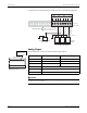
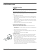
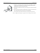
A typical connection and operational details are illustrated below..
NOTE
The mechanical relays should be protected by external fuses.
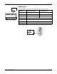
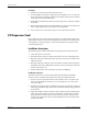
Solid-State Relay Outputs
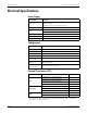
Specifications for the four digital relay (Form A) outputs (D1 through D4) are as
follows:
1
Digital output D4 is configured at the factory to emit pulses for calibration testing purposes.
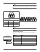
Operational Block Diagram
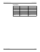
STATE RX1 – RX2 RX2 – RX3
Inactive Open Closed
Active Closed Open
Pulse
Closed for
duration of pulse
Open for duration
of pulse
R
X1
R
X2
R
X3
N/O N/C
R 11 R 12 R 13 R 21 R 22 R 23 R 31 R 32 R 33
Specification Value
Signal Type
Continuous or pulse
1
Maximum Load Voltage 30V
Maximum Load Current 80 mA
Isolation 5,000 Vrms
Scan Time ½ cycle
Connection Type Captured-wire
Wire Type AWG 28 to AWG 16
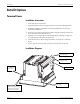
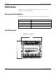
Rear View of Meter
Standard I/O
Solid-State relays