
- Power Measurement Modem User's Guide

Specifying a Port in an ION Module ION 7500 / ION 7600 User’s Guide
Page 140 Chapter 5 - Features and Applications
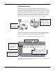
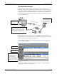
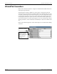
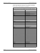
The following table describes the ports that can be configured (in the Digital
Output, Pulser, Digital Input, Analog Input, Analog Output, and Calibration
Pulser modules) to handle outgoing or incoming signals.
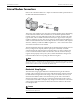
All ION 7500 and ION 7600 meters have these digital input/output ports. Optional
analog input/output ports and optional digital inputs are also available on both meters.
Standard Output Port Names Description
Port R1 Digital (Form C Relay) Output port 1
Port R2 Digital Output port 2
Port R3 Digital Output port 3
Port D1 Digital (Form A Solid-State) Output port 4
Port D2 Digital Output port 5
Port D3 Digital Output port 6
Port D4 Digital Output port 7
kWh Pulse –LED LED Output
Alarm LED LED Output
Optional Output Port Names Description
Port AO1 Analog Output port 1
Port AO2 Analog Output port 2
Port AO3 Analog Output port 3
Port AO4 Analog Output port 4
Standard Input Port Names Description
Port S1 Digital (Status) Input port 1
Port S2 Digital Input port 2
Port S3 Digital Input port 3
Port S4 Digital Input port 4
Port S5 Digital Input port 5
Port S6 Digital Input port 6
Port S7 Digital Input port 7
Port S8 Digital Input port 8
Optional Input Port Names Description
Port AI1 Analog Input port 1
Port AI2 Analog Input port 2
Port AI3 Analog Input port 3
Port AI4 Analog Input port 4
Port DI1 Digital (Status) Input port 9
Port DI2 Digital Input port 10
Port DI3 Digital Input port 11
Port DI4 Digital Input port 12
Port DI5 Digital Input port 13
Port DI6 Digital Input port 14
Port DI7 Digital Input port 15
Port DI8 Digital Input port 16