ENTR Wi-Fi Bridge integration Guide April, 24, 2017 ENTR Integration Bridge: 1 Wi-Fi Kit Integration Guide Wi- Revision 2.0 Date 24-04-17 Proprietary Notice The information contained in this document is proprietary to Mul-T-Lock. Use or transfer of this document or the information contained herein without the express written consent of Mul-T-Lock is prohibited.
ENTR Wi-Fi Bridge integration Guide April, 24, 2017 Rev Description Name Date 0.0 Initial David Termin 14-04-16 1.0 First release David Termin 26-04-16 David Termin 26-04-17 2.0 Change web configuration method to Mobile App.
ENTR Wi-Fi Bridge integration Guide April, 24, 2017 Table of Contents 1. Package contents........................................................................................................................................................4 2. HMI and Led Indicators.............................................................................................................................................4 3. Getting Started .................................................................................
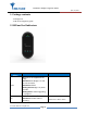
ENTR Wi-Fi Bridge integration Guide April, 24, 2017 1. Package contents 1 x Bridge unit. 1 x Wi Fi kit integration guide. 2. HMI and Led Indicators LED/Push Button Power BLE Description Remarks Off-Power is not supplied to the Bridge Solid Green-The Bridge is on and BIT was successful. Solid Red-BIT failed. Blinking Green-Bridge is in power up mode. Blinking Red-Firmware upgrading is in progress. Off-The BLE radio is off. Solid Green- The BLE radio is operating.
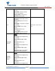
ENTR Wi-Fi Bridge integration Guide April, 24, 2017 Wi-Fi USB (ZigBee example) AA ZigBee (example) Module Blinking Green- Data is send or receives. Solid Amber: Joined a piconet network successfully. Blinking Amber: Scan activity Solid Red: Failed to pair. Off-The 2.4GHz radio is off. Solid Green- The 2.4GHz radio is operating. Blinking Green- Data is send or receives. Solid Amber: Joined Wi-Fi network successfully. Blinking Amber: Wi-Fi Tx/Rx activity. Solid Red: Failed to join Wi-Fi network.
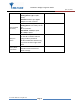
ENTR Wi-Fi Bridge integration Guide April, 24, 2017 Ethernet (RJ45 connector) WPS push Button Factory Reset push Button successfully Blinking Green: ZigBee TX/Rx activity. Solid Red: Failed to join ZigBee PAN/Parent node removed Solid Green- Link is up, no Activity. Blinking Green- Link activity on the port. Off- Link is down. Solid Yellow- 100Mbps speed. Off- 10Mbps speed. This button lets you use WPS to join the Wi-Fi network without typing the Wi-Fi password.
ENTR Wi-Fi Bridge integration Guide April, 24, 2017 3. Getting Started The Bridge is connecting to various ecosystem domains, the first one is BLE connectivity to the ENTR lock, the second is to the Wi-Fi home network and the last one is to the server (integrator cloud). In order to configure/pair all three of the above we are using dedicated configuration application. Assuming the ENTR DU is already paired to the smartphone the bridge is considered as an ENTR user and for that the ENTR App.
ENTR Wi-Fi Bridge integration Guide April, 24, 2017 3.
ENTR Wi-Fi Bridge integration Guide April, 24, 2017 Enter the user name, generate the key code, and share or remember the code for the process of getting the key through the Bridge unit. Press “Activate”.
ENTR Wi-Fi Bridge integration Guide April, 24, 2017 On Success you will see the following screen: From this moment, for the predefined expiration time, the key will be waiting in the lock (pending) until it will be pulled from the lock using this code. The key pulling can be done by the Bridge.
ENTR Wi-Fi Bridge integration Guide April, 24, 2017 3.2 Powering up the Bridge It is recommended that you first set up this Bridge somewhere close to the wireless router, and then move this Bridge to another location for optimal Wi-Fi reception. Insert the Bridge adaptor into the AC socket. The bridge will start powering up and the green power led will become steady if the BIT procedure passes successfully (picture 1).
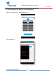
ENTR Wi-Fi Bridge integration Guide April, 24, 2017 3.3 Configuration the Bridge step by step 3.3.1 Configuration App. connecting to the Bridge Open the configuration application on your mobile phone. Picture 2. A welcome ENTR bridge set up appears. Now press the "Scan" button and wait for the app to connecting to the Bridge.
ENTR Wi-Fi Bridge integration Guide April, 24, 2017 Picture 3. After the App. is connecting to the Bridge successfully the App. updates its status to "You are now connected to ENTR Integration Bridge ENTR-I-BRIDGE". Remark: The same configuration application supports both integration and Tiny bridges. 3.3.2 Pairing the Bridge to the ENTR BLE domain After adding the bridge and generating a key per paragraph 3.1 we can start paring the bridge to the ENTR BLE domain.
ENTR Wi-Fi Bridge integration Guide April, 24, 2017 Picture 4. The App. is searching for locks that are in BLE range and have a pending key.
ENTR Wi-Fi Bridge integration Guide April, 24, 2017 Picture 5. The BLE LED blinks in Amber color that indicates that the bridge is searching for locks that are within BLE range and have a pending key.
ENTR Wi-Fi Bridge integration Guide April, 24, 2017 Picture 6. Select "Lock 121" from the list appears on the screen on picture 6. Picture 7.
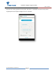
ENTR Wi-Fi Bridge integration Guide April, 24, 2017 Type your pin code that you received per paragraph 3.1.a connecting attempt will appears on your screen. Wait for successful connection and ensure that the BLE LED is steady state amber colored. 3.3.3 Pairing the Bridge to the Wi-Fi network domain Picture 8. Now we are ready to configure the Wi-Fi section of the bridge.
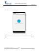
ENTR Wi-Fi Bridge integration Guide April, 24, 2017 Picture 9. Enter the Wi-Fi network password (SSID), a connecting attempt will appears on your screen. The Wi-Fi LED blinks in Amber color and wait for successful connection – Wi-Fi LED become steady state amber colored.
ENTR Wi-Fi Bridge integration Guide April, 24, 2017 3.3.4 Bridge to server configuration procedure The integrator has to enter the DNS server IP or URL address and port number (optional). Default port number is 40003. Press "Next" after filling both fields. When setup is done, the bridge will try to connect to the server. Make sure the server is up and running.
ENTR Wi-Fi Bridge integration Guide April, 24, 2017 4. For radio enclosure Federal Communications Commission (FCC) Statement labelling requirement for small device statement (FCC15.19 (3)) This device complies with part 15 of the FCC Rules. Operation is subject to the following two conditions: (1) This device may not cause harmful interference, and (2) this device must accept any interference received, including interference that may cause undesired operation. 4.
ENTR Wi-Fi Bridge integration Guide April, 24, 2017 Product FCC ID: 2AHH881134 4.3 Modifications (FCC 15.21) Changes or modifications to this equipment not expressly approved by Mul-T-Lock® may void the user’s authority to operate this equipment. 4.4 RF Exposure info (FCC 2.1093)-for module radio This equipment has been approved for mobile applications where the equipment should be used at distances greater than 20cm from the human body (with the exception of hands, wrists, feet and ankles).
ENTR Wi-Fi Bridge integration Guide April, 24, 2017 Appendix A WPS Configuration You can connect to the Bridge’s Wi-Fi network with Wi-Fi Protected Setup (WPS), to use WPS procedure do the following: Make sure that the Bridge has power (its green Power LED is lit steady). Press the WPS button on the Bridge for 3 seconds (WPS button is located on the bottom right of the Bridge) until the Wi-Fi white color led start blinking.