
User Manual


UGM Manual
Page 2 ArKion Systems – Confidential Rev 0.1
Atmega
128
uP
Meter interface &
Buffers
FLASH
Temp Sense
RTC
T/R
Switch
PWR
REG
IF1
10.7Mhz
Antenna
3.3V
3.3V
+3.3V
SPI
TEMP
RF
LNA
BATT
10.245
Mhz
TCXO
Super
caps
+5V
Serial data
7.3728
Mhz
Osc
RF211
RF RX
RF TX
32.768
Khz
Osc
RTC CLK
9-15V
Unreg
RF RX
CTRL
DATA
CTRL
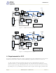
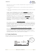
UGMLG Block Diagram
IF2
455Khz
MMCX Connector
To Electric Meter
Figure 1. UGM Low Block Diagram
Meter interface &
Buffers
T/R
Switch
PWR
REG
RF
LNA
CTRL
DATA
MMCX Connector
RF
PA
Figure 2. UGM High Block Diagram
4. Requirements for FCC
To ensure continuing adherence to FCC requirements for the UGM module used in various
Landis+Gry Focus meter forms all of the following requirements must be observed.
1) The antenna must be installed such that 20 cm is maintained between the
antenna and users. For laptop installations, the antenna must be installed to ensure
that the proper spacing is maintained in the event the users places the device in their
lap during use (i.e. positioning of antennas must be placed in the upper portion of the