
User Manual


MiHub 1.5 XR Installation & Operation Manual
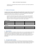
ThebottomoftheMiHub1.5XRhasapowercordattachedinthemiddle.Totheleftofthatisanair
vent.Totherightofthepo wer cordisthe915MHzantenna connection(N‐typefemale)andagreen
LEDtoindicatethattheunitispowered
up.OntherightsideistheGPRSantenna.
Apre‐drilledmountingplateis attachedtoboththetop&bottomofthemainunit.
Therearenoother(operator/installer)accessiblecon trolsordispla ys.
AnyuseoftheMiHub1.5XRproductinotherthantheintendedmannerspecified
bythemanufacturer
mayimpairtheprotectionprovidedbytheequipment.
Installationisachievedasfollows:
6.1 InstallationInstructions:
WARNING! Becausetheinstallationistypicallyconnectingthepowercordtolivepowerlines,
onlypersonneltrained&licensedproperlyforthelocaljurisdictionshouldperformthis
installation.
A.Pickasafelocationwherethepowercordcanreachtheinputpowersource.Installthe
MiHub1.5XRmainenclosurebyutilizingthescrews&thepre‐drilledmountingplateslocated
atthetop&bottomoftheenclosurebox.Keeptheboxvertical/plumbasmuchaspossible.
B.Connectthecolorcodedwirestothepowersource.Thisoperationshouldbeperformedbya
properlylicensedprofessional.Theblackwireisthepowerinput(nominally110VAC)&the
whitewireisreturn.
C.Afterconnectinginputpower,verifythatthegreenLEDonthebottomoftheenclosureislit.
D.Thiscompletesthephysicalinstallation.Fromthistimeforward,additionalstepstocontrol
theMiHub1.5XRarealldone
remotelyviatheGPRSRFlink.
7 Maintenance:
TherearenouserserviceableitemswithinaMiHub1.5XR.Nocleaningisrequired.