
Installation Manual


Mueller Cellular Node Installation
Manual
Mueller Systems – Proprietary
Page 6
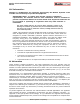
3.2 Exterior Wall Mounting
Tools required: 1 – 1 1/2 inch galvanized, or stainless wood or sheet
metal screws (2 per), Phillips screwdriver
1.
The open-ended wire from the device permits routing through
interior walls for external wall mounting when required or
direct mounting to exposed floor joists above grade level.
2.
Mueller Cellular Node can be directly mounted to almost any
flat surface by using the holes shown and common screws in
most instances.
3.
Vertical orientation of the device is required to maximize RF
performance.
3.3 Wiring
Tools Required: 3M-2Y connectors, splitting tube, and a 3M Crimping Tool
Mueller Cellular Node
Red
Green/White
Black
Translator Register
Red
Green/White
Black
Badger ADE Register
Red
Green
Black
Sensus ECR and ICE Registers
Red
Green
Black
Neptune PRORead, AUTORead, E-Coder Registers
Black
Red
Green
Table 1. Mueller Cellular Node Meter Interconnect
3.4 Verification- Activation [Bluetooth]
The EFR32 Bluetooth subsystem is primarily responsible for one time device activation and
verification. Device activation must be in close proximity of Mobile Bluetooth Hand-Held [<
5ft]
Device Bluetooth activation is initiated by a magnet swipe located in a pre-determined area
on the device.
After magnet swipe, device initiates Bluetooth communication and is configured in discovery
mode. For one time activation the Bluetooth Hand-held should be used to verify proper
installation and operation. Verify device operates per customer settings and is starting with
the default profile.
Bluetooth subsystem is deactivated after verification/activation and device enters normal
mode and supports the profiles based on situational logic.
Bluetooth subsystem will be shut down and non-functional until new activation is initiated
by local magnet swipe.
Please refer to the Bluetooth Mobile Hand-held application manual for more app. details.
Shipping mode -- How the device leaves the factory and shipped to a warehouse or
distribution center