
User's Manual

6
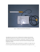
RFantennas.Thetopantenna(inthisexample)isfortheGPRS&thebottomisforthe
RFDC.Apre‐drilledmountingplateisattachedtoboththetop&bottomoftheCCOM.
Therearenoother(operator/installer)accessiblecontrolsordisplays.
AnyuseoftheCCOMproductin
otherthantheintendedmannerspecifiedbythe
manufacturermayimpairtheprotectionprovidedby theequipment.
Installationisachievedasfollows:
InstallationInstructions:
WARNING!Becausetheinstallationistypicallytoatelephonepole,orasimilarhighobject,
andinvolvesconnectingthepowercordtolivepowerlines,onlypersonneltrained&
licensedproperlyforthelocaljurisdictionshouldperformthisinstallation.
A. Pickasafepolelocationwherethepowercordcanreachtheinputpower
source.InstalltheCCOMtothetelephone(orotherwooden)polebyutilizingthe
screws&thepre‐drilledmountingplateslocatedatthetop&bottomofthe
CCOMbox.Keeptheboxvertical/plumbasmuchaspossible.
B. Connectthecolorcodedwirestothepowersource.Thisoperationshouldbe
performedbyaproperlylicensedprofessional.
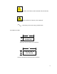
C. ColorCode:FortheCCOM_AC(hasablackjacketedpowercord),theblackwire
isthepowerinput(nominally110VAC)&thewhitewireisreturn.Forthe
CCOM_DC(hasayellowjacketedpowercord),thewhitewireisthepowerinput
(10‐30VDC)&theblackwireisreturn.
D. Afterconnectinginputpower,verifythatthegreenLEDonthebottomofthe
CCOMislit.
E. Thiscompletesthephysicalinstallation.Fromthistimeforward,additionalsteps
tocontroltheCCOMarealldoneremotelyvia
theGPRSRFlink.
4) Maintenance:
TherearenouserserviceableitemswithinaCCOM.Nocleaningisrequired.Thefuses&
batteriesshouldbereplacedbyproperlytrained&licensedpersonnelonly.These