CCOM Installation & Operation Manual 880‐0017‐001 Rev A04 Revision History Rev Description of change Changed by Effective Date A00 Originated & Released Bruggemann 04/08 A01 Updated to include FCC notices and labels Cullinan 12/08 A02 Minor Updates for FCC notices and external antenna Cullinan 12/08 A04 Minor Updates for FCC notices for antenna separation Cullinan 1/09 1
MANUFACTURER Arkion Systems 230 Union Street New Bedford MA, 02740 Table of Contents 1) Intended use ……………………………………………………………………………………..4 2) Environmental Caution ………………………………………………………………………4 3) Installation & Operation …………………………………………………………………….4 4) Maintenance ……………………………………………………………………………………..7 5) Labels & Locations ……………………………………………………………………………. 7 5.1 Explanations of Labels & Symbols ……………………………………………….. 8 5.2 CCOM Labels ………………………………………………………………………………. 8 5.3 Locations of CCOM Labels …………………………………………….
FCC Information Changes or modifications not expressly approved by the ArKion Systems could void the user's authority to operate the equipment. IMPORTANT NOTE: To comply with FCC RF exposure compliance requirements, the antenna used for this transmitter must be installed to provide a separation distance of at least 35 cm from all persons and must not be co‐located or operating in conjunction with any other antenna or transmitter.
1) Intended Use: The CCOM unit is intended for indoor & outdoor use as an unattended data collector for automatic meter metering & control applications. The unit is attached (hard wired) to an external power source, 10‐ 30 VDC, 15W for the CCOM_DC & 100‐240 VAC , 50/ 60 HZ, 15W for a CCOM AC. The external power hookup is to meet appropriate local & national electrical codes & be performed by an appropriately licensed professional.
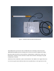
Figure 1: CCOM AC PWR with RFDC & GPRS options. The CCOM power input can be either 1030 VDC (for the CCOM_DC DC version) and 100240 VAC 50/60 HZ (for the CCOM_AC AC version). The external appearance will be identical except that the DC version will have a yellow power cord & the AC version has a black power cord. Both versions also have unique external stickers identifying the type & configuration of CCOM. The bottom of the CCOM has a power cord attached in the middle.
RF antennas. The top antenna (in this example) is for the GPRS & the bottom is for the RFDC. A pre‐drilled mounting plate is attached to both the top & bottom of the CCOM. There are no other (operator/installer) accessible controls or displays. Any use of the CCOM product in other than the intended manner specified by the manufacturer may impair the protection provided by the equipment.
replacements should only be performed after the unit has been removed from the input power source by personnel trained & licensed properly for the local jurisdiction. Used fuses & batteries should be disposed of properly. For all other maintenance issues consult manufacturer. The CCOM battery packs are available from the manufacturer.
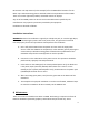
Caution, risk of electric shock (located at Shock Hazards) Label is defined as “Caution, refer to Manual” Alternating current (see rating / model Label) 5.2 CCOM Unit Labels: 1.00 .25 FUSE RATING 5A SLOW BLOW Slow Blow Fuse (located next to 5A fuse) 1.75 .
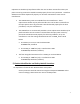
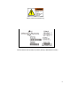
Electric Shock Hazard Warning Finished Goods Label (CCOM, AC, Battery‐backup, GPRS Modem shown) 9
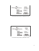
Finished Goods Label (CCOM, AC, GPRS Modem shown) Finished Goods Label (CCOM, DC, GPRS Modem shown) 10
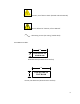
Battery Warning Labels 3.00 BATTERY WARNING DO NOT SHORT OUT - DO NOT PUT IN FIRE MAY RELEASE TOXIC MATERIALS OR CAUSE BURNS SEALED-LEAD BATTERY MUST BE RECYCLED OR DISPOSED OF PROPERLY 1.50 BATTERY WARNING LABEL #1 2.00 DANGER OF EXPLOSION 1.00 IF BATTERY IS INCORRECTLY REPLACED.
5.
Product & Electrical Shock Warning Label locations outside enclosure 13
5.
6) FCC Identification Labels This is illustration of FCC label for CCOM. Model CCOM FCC ID: SM6-CCOM-AC This device complies with Part 15 of the FCC Rules. Operation is subject to the following two conditions; (1) this device may not cause harmful interference, and (2) this device must accept any interference received, including interference that may cause undesired operation. Figure 1.