
Troubleshooting guide


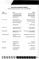

1. Fuses- For convenience, all amplifiers utilize ATC type fuses. For continued protection in the eventthat a fuse blows,
replace the fuse only with the same value.
Caution - The power fuses on the amp are for protecting the amp against overdrive. To protect the vehicle’s
electrical system, an additional fuse is required within 18” of the battery on the 12Vt cable.
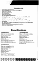
Thunder42500 - 20A x 2
Thunder65OOD - 25A x 3
Thunder81000D - 150 Amps (not supplied)
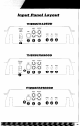
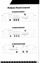
2. Power Terminal -This terminal is where the power source of the vehicle is connected. The 12Vt must be con-
nected directly to the positive battery post. It is highly recommended that you place an additional fuse within 18”
of the battery connection, Be sure to use the correct gauge of power cable! If wire of insufficient size is used,
there will be a voltage drop and the amp will starve, causing poor performance. In an extreme case, the amp may
shut down due to the low battery voltage protection feature. The terminal closest to the fuse(s) is where the power
cable with connector should be installed. Be sure to make your connection clean to avoid any shorting to the other
terminals. Always double check all of the connections for any discrepancies.08
Thunder42500 - 6-8 Gauge
Thunder6500D - 4-6 Gauge
Thunder81000D - l/O Gauge only
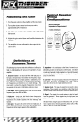
3. Remote Terminal-This is the wire thatturns the amplifier on and off. This terminal connects to the amp turn-on lead
or the power antenna lead coming from the source unit. If the source unit doesn’t have one of these wires, you can
either run a wire to the battery with a switch or use an ignition controlled wire to power up the amp. If you use the
ignition controlled wire, be aware that the amplifier will be on, as long as the car is on. When using the Smart
Engage” feature, a high powered radio, and speaker level inputs it is not necessaryto connectthe Remote Terminal.
4. Ground Terminal -The ground terminal connects the amplifier to the vehicle ground. Be sure to use the same size
wire gauge or larger as the t12V connection. A strong ground point is very important. A little screw through the body
is not acceptable. The cable should be as short as possible and connected to the chassis of the vehicle. The contact
point should be free of paint and debris for best results. All precautions for the 12Vt connection apply to this con-
nection as well.
5. Power LED (top oi heatsink)- A lighted LED indicates that power has been applied to the amplifier. t12V from the
battery to the tBAll terminal (#lo) and t12V from a switched ignition or remote lead from a head unit. An
unlighted LED indicates power has been removed or the amplifier has overheated. In the case of the overheat
condition, the amplifier will turn back on after it cools down.
P
6. 4 Term Block- The t and - terminals connect the speaker to the amplifier. 2 ohm minimum
impedance is allowed.