
Manual
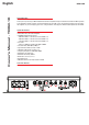
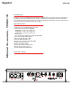
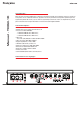

Control Panel
Gain Control (GAIN): The gain control matches the input sensitivity of the amplier to the source unit being used.
The operating range varies from 250mv to 5V.
Adjusting the gain
1. Turn the gain control on the amplier all the way down (counter clockwise).
2. Turn up the volume control on the source unit to approximately 3⁄4 of maximum.
3. Adjust the gain control on the amplifier until clip light illuminates and then reduce until light turns off.
4. Adjust the gain control down until audible distortion disappears.
5. The amplifier is now calibrated to the output of the source unit.
Bass Boost Control (BASS BOOST):
Allows user to adjust the bass boost between 0dB - 12dB at 40Hz.
Subsonic Filter Control (SUB SONIC):
Used to select the desired subsonic lter frequency. The frequency is adjustable from 20Hz to 50Hz.
Low Pass X-Over Frequency Control (LPF) :
Used to select the desired low-pass (LP) x-over frequency. The frequency is adjustable from 40Hz to 200Hz.
RCA Inputs (INPUT): These RCA inputs are used with source units that have either RCA/Line level or speaker level
outputs. (Source units need a minimum level of 250mV output for proper operation of the amplier).
MTX recommends only high quality twisted pair cables (such as StreetWires) to decrease the possibility of radiated
noise entering the system.
EBC Port (External Bass Control) - The EBC plugs directly into this port, and the EBC should be plugged in and set
to Max if used while setting gain. While the EBC itself can be placed anywhere in the vehicle for on demand bass
adjustments. EBC is included.
LED Indicators - Your TH amplier is equipped with 3 LED indicators, Power, Protect, and Clip.
• The Power LED will illuminate when the unit has power from a 12V source and 12V is applied to the remote terminal.
• The Protect LED will illuminate when the amplier enters protect mode due to an electrical short or excessive
thermal incident (see Troubleshooting).
• The Clip LED light is connected to the gain control of the amplier. This LED will illuminate when the amplier
has reached its RMS power output based on the attached speaker load (impedance). If this LED is illuminated
the amplier is running outside of its recommended conguration and requires adjustment. For optimal
performance, the gain should be reduced until this LED light turns off.
Speaker Terminals (SPEAKER TERMINALS) : Connect speakers to these terminals. Observe speaker polarity
throughout the system. Improper phase can result in loss of bass response and/or poor overall sound quality.
Ground Terminal (GND) : A proper ground is required for your amplier to operate at peak performance. A short
ground cable the same diameter as the power cable should be used to attach the ground terminal directly to the
chassis of the vehicle. Always remove paint, dirt or debris to expose bare metal where the ground will be attached.
Power Terminal (+BATT) : This is the main power input for the amplier and must be connected directly to the
positive terminal of the vehicles battery for proper operation. Use caution when installing (+12) power cable in the
vehicle. Avoid running this cable parallel with RCA cables, antennas, or other sensitive equipment due to massive
currents that can induce noise into the audio system. It is also very important to have a tight, secure connection for
maximum performance. MTX recommends using 4 AWG power wire with the MTX TH350.1D amplier
Remote Terminal (REM) : The amplier is turned on by applying 12 volts to this terminal. Typically this voltage is
supplied by a wire from the source unit marked “remote” or “power antenna”.
Fuses (FUSE) : If the fuse blows, replace with the same value. Never use a higher rated fuse!