Instruction Manual
Table Of Contents
- Contents
- Technical Support
- Preface
- Hardware Overview
- Software Utilities
- Setting up the Transducer Interface
- Installing the Transducer
- Contents
- Hazard Icon
- Road and Track Vehicles
- Road Simulator
- Analyzing SWIFT Data
- Maintenance
- Troubleshooting
- Assembly Drawings

Road Simulator
SWIFT 10 ATV Sensors Installing the Transducer
93
Note The encoder has a dot on the mounting flange connected to the slip-ring
bracket and another dot on the slip-ring connector housing where it
interfaces with the mounting flange. These dots, when aligned next to
each other, indicate the index mark is under the encoder sensor.
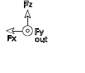
2. Rotate the adapter plate, as necessary, until the Fz on the axes icon (see the
next figure) printed on the transducer label is pointing up.
3. If not already assembled, attach the inclinometer to the level bracket using
the two 6-32 UNC fasteners provided.
Apply Locktite 222 to the threads on the fasteners. Torque each fastener to 2
N•m (18 lbf•in).
Axes Icon
S20-22


