
User Manual


Table Of Contents
- Technical Support
- Preface
- Introduction
- Overview Reference
- Series 647 Hydraulic Wedge Grips Component Identification
- Series 647 Hydraulic Wedge Grips Functional Description
- About Gripping Specimens
- About Wedges
- About Spiral Washers
- About Couplings
- About All Temperature Grips
- About Environmental Chambers
- Hydraulic Fluid Recommendations
- Cooling Water Specifications
- Series 647 Wedge Grip Temperature Ranges
- Series 647 Hydraulic Wedge Grip Force and Torque Capacities
- Safety
- General Safety Practices: Grips and Fixtures
- Read all manuals
- Avoid Pinch and Crush Points
- Locate and read hazard placards/labels
- Know facility safe procedures
- Know controls
- Know Specimen Properties
- Have first aid available
- Be aware of component movement with hydraulics off
- Keep bystanders safely away
- Wear proper clothing
- Remove flammable fluids
- Check bolt ratings and torques
- Lift Equipment Safely
- Practice good housekeeping
- Do not exceed the Maximum Supply Pressure
- Do not disable safety devices
- Provide adequate lighting
- Provide means to access out-of-reach components
- Wear appropriate personal protection
- Handle chemicals safely
- Know system interlocks
- Know system limits
- Do not disturb sensors
- Ensure secure cables
- Stay alert
- Contain small leaks
- Stay clear of moving equipment/avoid crush points
- Know the causes of unexpected actuator motions
- General Precautions for Environmental Components
- Hazard Placard Placement
- General Safety Practices: Grips and Fixtures
- Installation
- Operation
- Maintenance
b) If necessary, remove the wedges from each grip. Go to “Change Wedges 647.02 - 647.100” and return
to this procedure when done.
c) Separate the hydraulic chamber from the grip assembly. Remove the socket head bolt which secures
the piston extension to the hydraulic chamber. Perform this step for both grips.
d) If necessary attach a strap wrench to the cylinder and the hydraulic chamber. Unscrew the hydraulic
chamber from the cylinder. Perform this step for both grips.
e) Clean and lubricate all of the surfaces that will contact each other (screw threads, spacers, and so
forth).
f) Clean the surfaces with alcohol or similar decreasing solvent. See “Temperature ranges” for the
recommended lubricant.
3. Mount the hydraulic chamber of the lower grip to the actuator piston rod using the appropriate stud, shims,
and spiral washers.
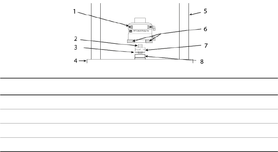
DescriptionItemDescriptionItem
Load Unit Columns5Hydraulic Chamber1
Lifting Device6Connector Stud2
Spiral Washers7Shim Washer3
Actuator Rod8Load Unit Base Plate4
a) Thread the connector stud into the hydraulic chamber of the lower grip. The connector stud should turn
freely. If any resistance is encountered, disassemble and correct the problem before proceeding.
b) Add any required shims, spacer, or spiral washers to the stud.
The attachment kit drawing shows what components (such as shims, spiral washers, and so forth)
should be installed.
c) Position the lower grip to align it with the connecting stud and stabilize the grip.
• Place appropriately sized wood blocks across the load unit base plate, on opposite sides of the
actuator piston rod.
• For heavy grips, insert the double swivel eyebolts into the threaded holes provided on the grip
chamber. Attach a lifting device to the double swivel eyebolts and carefully raise the grip.
58 Series 647 Hydraulic Wedge Grips Reference Manual
Installation