
User Manual


Table Of Contents
- Technical Support
- Preface
- Introduction
- Overview Reference
- Series 647 Hydraulic Wedge Grips Component Identification
- Series 647 Hydraulic Wedge Grips Functional Description
- About Gripping Specimens
- About Wedges
- About Spiral Washers
- About Couplings
- About All Temperature Grips
- About Environmental Chambers
- Hydraulic Fluid Recommendations
- Cooling Water Specifications
- Series 647 Wedge Grip Temperature Ranges
- Series 647 Hydraulic Wedge Grip Force and Torque Capacities
- Safety
- General Safety Practices: Grips and Fixtures
- Read all manuals
- Avoid Pinch and Crush Points
- Locate and read hazard placards/labels
- Know facility safe procedures
- Know controls
- Know Specimen Properties
- Have first aid available
- Be aware of component movement with hydraulics off
- Keep bystanders safely away
- Wear proper clothing
- Remove flammable fluids
- Check bolt ratings and torques
- Lift Equipment Safely
- Practice good housekeeping
- Do not exceed the Maximum Supply Pressure
- Do not disable safety devices
- Provide adequate lighting
- Provide means to access out-of-reach components
- Wear appropriate personal protection
- Handle chemicals safely
- Know system interlocks
- Know system limits
- Do not disturb sensors
- Ensure secure cables
- Stay alert
- Contain small leaks
- Stay clear of moving equipment/avoid crush points
- Know the causes of unexpected actuator motions
- General Precautions for Environmental Components
- Hazard Placard Placement
- General Safety Practices: Grips and Fixtures
- Installation
- Operation
- Maintenance
3.
Warning:
The upper grips are very top heavy and will have a tendency to tip over when lifted by the
double swivel eyebolts.
Dropped grips can cause injury to personnel and damage to equipment.
Never attempt to control the grip by holding onto the eyebolts. Use the connector stud to help
control the grip balance.
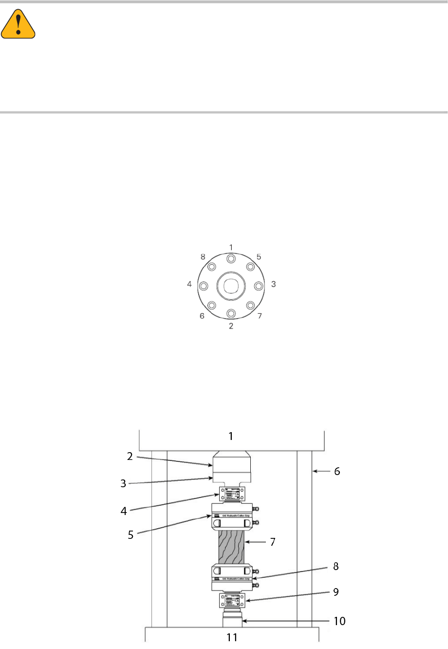
Mount the upper grip to the force transducer on the crosshead using an adapter between the force
transducer and the upper grip.
a) Place the load transducer mating adapter against the force transducer and thread the socket head cap
screws into the force transducer until they are finger tight.
b) Using the sequence shown in the figure to the right, torque the socket head screws first to 10%, then
to 50%, and finally to 100% of the torque specified on the attachment kit drawing (MTS part number
469615-xx).
c) Remove the socket head cap screws from the upper coupling and place the screws and coupling halves
within easy reach and oriented properly for installation on the grips.
d) Place a wooden spacer (a wood block or piece of plywood) on top of the lower grip. The wooden spacer
should be large enough to cover the diameter of the grip.
48 Series 647 Hydraulic Wedge Grips Reference Manual
Installation