
User Manual


Table Of Contents
- Technical Support
- Preface
- Introduction
- Overview Reference
- Series 647 Hydraulic Wedge Grips Component Identification
- Series 647 Hydraulic Wedge Grips Functional Description
- About Gripping Specimens
- About Wedges
- About Spiral Washers
- About Couplings
- About All Temperature Grips
- About Environmental Chambers
- Hydraulic Fluid Recommendations
- Cooling Water Specifications
- Series 647 Wedge Grip Temperature Ranges
- Series 647 Hydraulic Wedge Grip Force and Torque Capacities
- Safety
- General Safety Practices: Grips and Fixtures
- Read all manuals
- Avoid Pinch and Crush Points
- Locate and read hazard placards/labels
- Know facility safe procedures
- Know controls
- Know Specimen Properties
- Have first aid available
- Be aware of component movement with hydraulics off
- Keep bystanders safely away
- Wear proper clothing
- Remove flammable fluids
- Check bolt ratings and torques
- Lift Equipment Safely
- Practice good housekeeping
- Do not exceed the Maximum Supply Pressure
- Do not disable safety devices
- Provide adequate lighting
- Provide means to access out-of-reach components
- Wear appropriate personal protection
- Handle chemicals safely
- Know system interlocks
- Know system limits
- Do not disturb sensors
- Ensure secure cables
- Stay alert
- Contain small leaks
- Stay clear of moving equipment/avoid crush points
- Know the causes of unexpected actuator motions
- General Precautions for Environmental Components
- Hazard Placard Placement
- General Safety Practices: Grips and Fixtures
- Installation
- Operation
- Maintenance
a) Remove the socket head cap screws from the lower coupling and place the screws and coupling halves
within easy reach and oriented properly for installation on the grips.
Note:
The label on the coupling indentifies which component should be connected to each side of the
coupling. Each end of the coupling has different threads.
b) Position the lower grip to align it with the connecting stud and stabilize the grip.
• Place appropriately sized wood blocks across the load unit base plate, on opposite sides of the
actuator piston rod.
• For heavy grips, insert the double swivel eyebolts into the threaded holes provided on the grip
chamber. Attach a lifting device to the double swivel eyebolts and carefully raise the grip.
c) Select the lower grip coupling set. Place the lower grip coupling half with the threaded holes against
the actuator and grip threads. Rotate it back and forth, as necessary, until the threads mesh with the
actuator and grip threads.
d) Place the other coupling half against the actuator and grip threads. While holding the two halves together
thread the socket head cap screws into the coupling until they are finger tight.
e) Check both ends of the coupling to ensure that the gap between the two halves is approximately equal.
If necessary, tighten and loosen the socket head cap screws to achieve this.
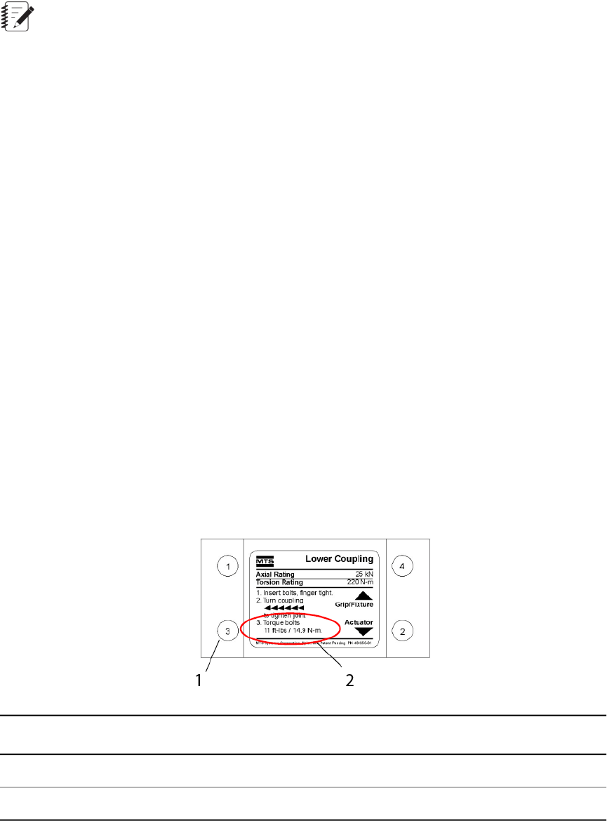
f) Find the label on the coupling. This label indicates the direction to tighten, the rotation pattern for
tightening the cap screws, and other important information. The illustration is an example only.
g) With all the socket head cap screws finger tight, rotate the coupling assembly in the direction shown
on the coupling label until it is tight. This preloads the grip connection.
h) Tighten the socket head cap screws in the order shown on the coupling label, first to 10%, then to 50%,
and finally to 100% of the specified torque.
DescriptionItem
Numbers show the rotation pattern.1
Full (100%) torque listed here.2
Series 647 Hydraulic Wedge Grips Reference Manual 47
Installation