
User Manual


Table Of Contents
- Technical Support
- Preface
- Introduction
- Overview Reference
- Series 647 Hydraulic Wedge Grips Component Identification
- Series 647 Hydraulic Wedge Grips Functional Description
- About Gripping Specimens
- About Wedges
- About Spiral Washers
- About Couplings
- About All Temperature Grips
- About Environmental Chambers
- Hydraulic Fluid Recommendations
- Cooling Water Specifications
- Series 647 Wedge Grip Temperature Ranges
- Series 647 Hydraulic Wedge Grip Force and Torque Capacities
- Safety
- General Safety Practices: Grips and Fixtures
- Read all manuals
- Avoid Pinch and Crush Points
- Locate and read hazard placards/labels
- Know facility safe procedures
- Know controls
- Know Specimen Properties
- Have first aid available
- Be aware of component movement with hydraulics off
- Keep bystanders safely away
- Wear proper clothing
- Remove flammable fluids
- Check bolt ratings and torques
- Lift Equipment Safely
- Practice good housekeeping
- Do not exceed the Maximum Supply Pressure
- Do not disable safety devices
- Provide adequate lighting
- Provide means to access out-of-reach components
- Wear appropriate personal protection
- Handle chemicals safely
- Know system interlocks
- Know system limits
- Do not disturb sensors
- Ensure secure cables
- Stay alert
- Contain small leaks
- Stay clear of moving equipment/avoid crush points
- Know the causes of unexpected actuator motions
- General Precautions for Environmental Components
- Hazard Placard Placement
- General Safety Practices: Grips and Fixtures
- Installation
- Operation
- Maintenance
• Smooth surfaces can grip specimens that cannot tolerate imperfections on the grip surface. This surface
also has a lower force rating.
Water-cooled wedges are available for applications where the specimen is heated. A water cooling kit includes
the parts to connect the wedges to a water source and regulate the water flow.
About Spiral Washers
The optional Model 601 Spiral Washers are commonly used when installing axial grips. They provide
fatigue-resistant connections between elements of the force train and minimize the effects of backlash.
The spiral washers are placed over the connector studs at each connection and adjusted to place a constant
preload on the stud. The spiral washers also minimize the possibility of backlash due to loose-fitting or worn
stud threads. When cyclic loads below the tensile force level of the preload are applied to the connections,
the load is distributed between the surfaces of the spiral washers and the stud in a ratio of the relative stiffness
of the parts. The spiral washers have a large surface area and therefore greater stiffness. They react to most
of the load and keep the stress in the stud below its fatigue runout level.
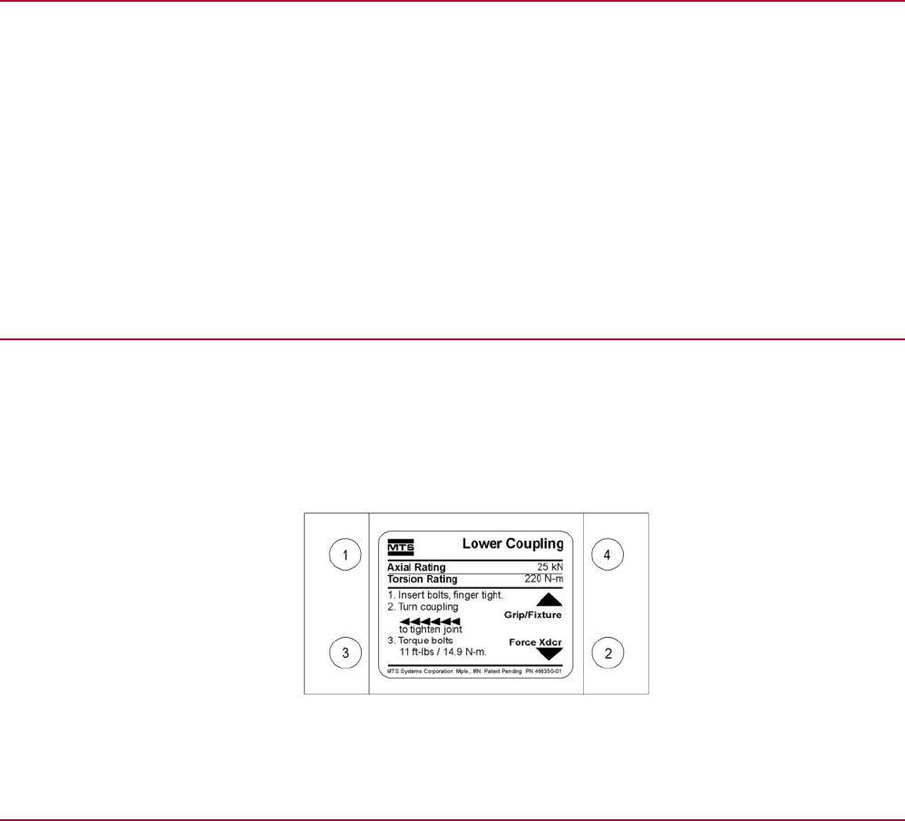
About Couplings
Special upper and lower couplings clamp the grips to the actuator and force transducer for axial-torsional
grips. Each coupling has two different thread patterns—a right-hand thread with a 3 mm pitch, and a left-hand
thread with a 2 mm pitch. Half of the coupling matches the thread of the grip, and the other half matches the
thread of the actuator or force transducer adapter. A label on each coupling indicates the direction to tighten,
torque rotation, and torque requirements. Here is an example:
About All Temperature Grips
The grip mechanism (the wedge chamber and wedges) is fully enclosed in the environmental chamber to
secure the specimen under test. The grip actuating mechanism (the end cap, preload chamber, and piston)
is outside the environmental chamber, eliminating the need for high-temperature hydraulic fluid and allowing
a broader temperature range for testing—from -129° to +315°C (-200° to +600°F) or -129° to +540°C (-200°
to +1000°F) depending on the grip model. With the grip mechanism inside the environmental chamber, the
thermal stresses caused by temperature gradients along the length of the specimen are minimized. The grip
actuating mechanism is water cooled/warmed to further protect it from temperature extremes.
Series 647 Hydraulic Wedge Grips Reference Manual 21
Introduction