
User guide


Aligning the Force Transducer
Series 311 Load Frame Maintenance
65
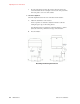
5. Finish the procedure.
In this step, you complete the force transducer alignment procedure.
A. Remove the dial indicator.
B. If you reduced pressure at the hydraulic power unit, restore full
hydraulic pressure.
C. Turn the load frame’s hydraulic pressure to off.
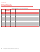
Cap Screw Torque Specifications
load cell
*
* Cap screw specifications for the Model 311.61 and 311.71 Load Frames
are contained on the drawings and parts lists for the specific unit.
Cap Screw Size Torque
311.11
†
† with a 100 kN (22 kip) force transducer
5/8-11
70 N
•m (52 lb•ft)
311.11
‡
‡ with a 250 kN (55 kip) force transducer
5/8-11
176 N
•m (130 lb•ft)
311.21) 1-8 UNC-2A
570 N•m (420 lb•ft)
311.31 1-8 UNC-2A
635 N•m (470 lb•ft)
311.41
§
§ with a 1500 kN (330 kip) force transducer
1-1/2-6
1220 N
•m (900 lb•ft)
311.41
#
# with a 2500 kN (550 kip) force transducer
1-1/2-6
1760 N•m (1300 lb•ft)
311.51 1-1/2-6 UNC-2A
1490 N•m (1100 lb•ft)