
Instruction Manual


Functional Description
512.14 Hydraulic Power Unit Introduction
9
Electronics The HPU has basic controls to turn it on to low pressure or high pressure and to
turn it off. The HPU includes an Emergency Stop switch that is connected to the
interlock chain of your test system.
A hydraulic interlock can be generated by the hydraulic power supply if one of
the following occurs:
• Low hydraulic fluid level
• High hydraulic fluid temperature
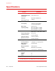
Hydraulic schematic The hydraulic schematic shows how the hydraulic components are connected in
the Model 512.14 Hydraulic Power Unit. Both types of heat exchangers are
shown.
Return -8
37° JIC Flare
Pressure -8
37° JIC Flare
Drain -06
SAE
0.125
1/2 NPT
Strainer
Pressure
Gage
Motor
Pump
Low Fluid
Switch
See Heat
Exchangers
Pressure
Relief
Valve
0.714 MPa
(1002000 psi)
Fan and Motor
Air-Cooled
Heat Exchanger
Water In
1/2 ID Hose
Water Out
1/2 ID Hose
Water-Cooled
Heat Exchanger
High/Low
Pressure
Solenoid
Filter
Check
Valve
Overtemperature
Switch
Reservior