MTS Acumen™ Electrodynamic Test System Load Frame User Guide 100-265-568 B be certain.
© 2014 MTS Systems Corporation. All rights reserved. Original Instructions (English): 100-265-568 B—January 2014 Trademark Information MTS, be certain., Bionix, ElastomerExpress, FlatTrac, FlexTest, Just In Case, LevelPlus, MTS Criterion, MTS EM Extend, MTS Insight, MTS Landmark, RPC, ServoSensor, SWIFT, Temposonics, TestWare, TestWorks are registered trademarks of MTS Systems Corporation within the United States.
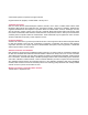
Contents Technical Support 5 How to Get Technical Support.................................................................................................................5 Before You Contact MTS.........................................................................................................................5 If You Contact MTS by Phone.................................................................................................................7 Problem Submittal Form in MTS Manuals..............
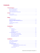
Grounding Information..............................................................................................................38 Connector Pinouts......................................................................................................................38 System Load Cell Mounting.......................................................................................................41 Accessory Mounting Dimensions................................................................................
Technical Support How to Get Technical Support Start with your manuals The manuals supplied by MTS provide most of the information you need to use and maintain your equipment. If your equipment includes software, look for online help and README files that contain additional product information. Technical support methods MTS provides a full range of support services after your system is installed. If you have any questions about a system or product, contact Technical Support in one of the following ways.
When you have more than one MTS system, the system job number identifies your system. You can find your job number in your order paperwork. Example system number: US1.
If You Contact MTS by Phone A Call Center agent registers your call before connecting you with a technical support specialist. The agent asks you for your: • Site number • Name • Company name • Company address • Phone number where you can be reached If your issue has a notification number, please provide that number. A new issue will be assigned a unique notification number.
After you call MTS logs and tracks all calls to ensure that you receive assistance for your problem or request. If you have questions about the status of your problem or have additional information to report, please contact Technical Support again and provide your original notification number.
Preface Before You Begin Safety first! Before you use your MTS product or system, read and understand the safety information provided with your system. Improper installation, operation, or maintenance can result in hazardous conditions that can cause severe personal injury or death, or damage to your equipment and specimen. Again, read and understand the safety information provided with your system before you continue. It is very important that you remain aware of hazards that apply to your system.
Warning: Warning notices indicate the presence of a hazard with a medium level of risk which, if ignored, can result in death, severe personal injury, or substantial property damage. Caution: Caution notices indicate the presence of a hazard with a low level of risk which, if ignored, could cause moderate or minor personal injury or equipment damage, or could endanger test integrity.
Hypertext links The electronic document has many hypertext links displayed in a blue font. All blue words in the body text, along with all contents entries and index page numbers, are hypertext links. When you click a hypertext link, the application jumps to the corresponding topic.
Safety Topics: • General Safety Practices.......................................................................................................................14 • Safety Practices Before System Operation...........................................................................................15 • Safety Practices While the System Is in Operation...............................................................................17 • Crush Zone.............................................................
Safety General Safety Practices This section provides information about safety issues that pertain to electrodynamic systems in general. These issues include statements to the intended use and foreseeable misuse of the system, the hazard zone, definition for the graphical hazard labeling that is affixed to your product, and other (more general) safety information that relates to the high-performance characteristics of MTS electrodynamic systems.
Safety • Facility variables (facility variables include the structure, atmosphere, and utilities) • Unauthorized customer modifications to the equipment • Operator experience and specialization • Test specimens Because of these variables (and the possibility of others), your system can operate under unforeseen circumstances that can result in an operating environment with unknown hazards.
Safety they require. If any control function or operating adjustment is not clear, review the applicable information until you understand it thoroughly. Have first aid available Accidents can happen even when you are careful. Arrange your operator schedules so that a properly trained person is always close by to render first aid. In addition, ensure that local emergency contact information is posted clearly and in sight of the system operator.
Safety Protect hoses and cables Protect electrical cables from excessive temperatures that can cause the cables to harden and eventually fail. Ensure that all cables have appropriate strain relief devices installed at the cable and near the connector plug. Do not use the connector plug as a strain relief. Protect all system hoses and cables from sharp or abrasive objects that can cause the hose or cable to fail. Never walk on hoses or cables or move heavy objects over them.
Safety Wear appropriate personal protection equipment (gloves, boots, suits, respirators) whenever you work with fluids, chemicals, or powders that can irritate or harm the skin, respiratory system, or eyes. Provide test area enclosure Use protective enclosures such as cages, guards, and special laboratory layouts when you work with hazardous test specimens (for example, brittle or fragmenting materials or materials that are internally pressurized).
Safety Contain small leaks Do not use your fingers or hands to stop small leaks in pneumatic hoses. Substantial pressures can build up, especially if the hole is small. These high pressures can cause the gas to penetrate your skin, causing painful and dangerously infected wounds. Turn off the pneumatic supply and allow the pneumatic pressure to dissipate before you remove and replace the hose or any pressurized component.
Safety Crush Zone of an MTS Acumen System Warning: Applying power can result in sudden actuator motion. A moving actuator can injure anyone in its path. Always clear the actuator area before applying power.
Safety Crosshead Emergency Operation The load frame has a manual lift actuation feature. It consists of manual method to turn the lift drive system if the load frame or lift system lose power. In such an event, an external 10mm hex bolt can be accessed from the underside of the crosshead. A 10mm socket wrench is required to actuate the lift system. The label shows which direction to turn the wrench to either raise or lower the crosshead.
Safety Location of Hex Bolt on Bottom of Crosshead To adjust the crosshead manually: 1. Turn the left and right crosshead locks into the fully unlocked position. 2. Using a 10 mm socket wrench, turn the manual crosshead adjustment hex bolt counter-clockwise to raise the crosshead, and turn it clockwise to lower the crosshead. Hazard Icons Following are the typical hazard icons used on MTS Acumen load frames. Item Description 1 2 3 Read manuals. Crush point. Tipping hazard.
Safety Item Description 4 5 6 7 No user-serviceable parts. Disconnect power before service. Electrical shock hazard. Electrical shock timer; value indicates number of seconds electrical shock hazard exists after system power is disconnected. Redundant protective earth ground connection required. Consult manual for instructions. Lift hole with thread size.
Introduction Topics: • Purpose .................................................................................................................................................26 • Load Frame Dimensions........................................................................................................................
Introduction Purpose The purpose of this manual is to help you understand your load frame, its capabilities, and operating requirements. This manual provides information for both MTS Acumen Electrodynamic Test Systems: 1.25 kN and 3.0 kN. Read each section carefully and refer to the manual whenever you need assistance.
Introduction Two-Column Load Frame Two-Column Load Frame Description Item Description 1 Actuator and power electronics (behind hood). 2 Columns on which the crosshead moves up and down. 3 Actuator rod. 4 Manual crosshead locks. Crosshead locks must be in a fully locked position to run a test. 5 Frame-mounted control. 6 T-slot base plate. 7 Load cell mounted on table top (load cell can also be mounted on the actuator). 8 Crosshead lift.
Introduction Item Description Red or White (Flashing) System is in service mode. To move the system out of service mode, slide the Service Mode switch on the upper back of the system, and click Interlock Reset. If problems continue, contact MTS Technical Support. White (Solid) Interlock cleared, standby power is on. Blue (Flashing) Interlock cleared, low power. Blue (Solid) Interlock cleared, high power, not running. Green (Solid) Interlock cleared, running state.
Introduction Item Description automatically turned off in order to prevent damage to the system. Load Frame Dimensions Note: Specifications subject to change without notice.
Introduction Load Frame Specifications Dimension Description MTS Acumen 1 MTS Acumen 3 A Minimum test space height 26 mm (1.02 in) 26 mm (1.02 in) A Maximum test space height 603 mm (23.74 in) 819 mm (32.24 in) B Working height 133 mm (5.24 in) 133 mm (5.24 in) C Test space width 375 mm (14.75 in) 460 mm (18.11 in) D Column diameter 63.5 mm (2.5 in) 63.5 mm (2.5 in) E Footprint width 550 mm (21.65 in) 634 mm (24.96 in) F Footprint depth 485 mm (19.09 in) 501 mm (19.
Introduction Electrical connections must be made by qualified personnel and conform to local codes and regulations. Local electrical codes supersede any information found here. Electrical Requirements MTS Acumen 1 MTS Acumen 3 Voltage 100-120 VAC (200-240) 200-240 VAC Frequency 50-60 Hz 50-60 Hz Current 7 (4) Amp 10 Amp Phase Single Single 7 MTS Acumen Force Ratings Note: Specifications subject to change without notice.
Introduction Note:The specifications above are for 25°C (75°F) ambient temperature. MTS Acumen Noise Level Note: Specifications subject to change without notice. Noise Level Noise Level 11 Typical 12 Maximum 11 12 MTS Acumen 1 MTS Acumen 3 47 dbA 47 dbA 69 dbA 69 dbA Typical usage at 1 m, free field. Noise level varies depending upon test type, specimen, environment, and other factors. Typical usage at 1 m, free field.
Installation Topics: • Frame Location and Ventilation.............................................................................................................34 • Environmental Requirements................................................................................................................34 • Interlock Logic........................................................................................................................................35 • Load Frame Connections.................
Installation Frame Location and Ventilation To ensure proper ventilation, locate the load frame approximately 300 mm (12 inches) from adjacent walls and equipment. Allow approximately 1 m (3 feet) behind the equipment for service access. Do not block the vent holes on the sides or back of the frame. For comfortable working conditions and proper equipment operation, heat dissipation of the equipment must be considered in providing adequate heating or air conditioning in the laboratory area.
Installation Interlock Logic Item Description 1 D9S 2 D9P 3 (Safety A+) 4 (Safety B+) 5 Custom Test Area Enclosure Switch 6 (Safety B) 7 (Safety A) 8 Test Area Enclosure 9 MTS Acumen Frame Load Frame Connections Connecting the Main Power The input voltage of MTS Acumen 1 frame is single phase 100-120 V /200-240 V, 50-60 Hz. The input voltage of MTS Acumen 3 frame is single phase 200-240 V, 50-60 Hz.
Installation Note: Local electrical codes supercede any information found here. Customers should use the power cord kit supplied by MTS for connecting electrical power and ground to the load frame. Use of power cords with inadequate ratings that are not equivalent to the power cord provided with your MTS Acumen product could cause a dangerous situation.
Installation Electrical Disconnect Ensure that there is access and adequate room behind the frame to allow electrical disconnection of the power cord. Disconnect the power cord before cleaning or inspecting any part of the test frame. When the hard cord kit option is used, the customer is responsible for providing an electrical power disconnect that is easy to operate and easy to reach. It must also meet IEC 60947-1 and IEC 60947-3 standards.
Installation Item Name 5 494.26 Position 2 6 494.27 Position 1 7 494.27 Frame Status 8 Grips 9 D/A Act. Cmd. 10 J23 Prog. Status 11 J29 Frame Interlocks 12 Frame Control 13 494.47 Frame Control 14 Enclosure Switch 15 J28 Actuator Enable 16 J43 Interlock Status 17 Remote E-Stop Grounding Information All equipment related to the load frame should be connected to the same electrical circuit if possible.
Installation Pin Signal 4 FB+ 5 FB- 6 No Contact 7 Shield 8 TEDS data 9 No Contact 10 EXS+ 11 No Contact 12 RCAL1 (FBR+) 13 RCAL2 (FBR-) 14 TEDS ground 15 EXSRemote E-Stop (D15S) Pin Signal 1 ESTOPB_OUT- 2 No Contact 3 ESTOP_OUT_MONITOR- 4 ESTOP_OUT_MONITOR+ 5 ESTOPB_IN+ 6 ESTOPA_OUT- 7 ESTOPB_IN- 8 ESTOPA_IN+ 9 ESTOPA_IN+ 10 No Contact 11 No Contact 12 No Contact 13 ESTOPA_IN- MTS Acumen™ Electrodynamic Test System 39
Installation Pin Signal 14 ESTOPA_OUT+ 15 No Contact Note:If E-STOP_OUT is not used, pins 3 and 4 must be jumpered together.
Installation System Load Cell Mounting The System Load Cell has two mounting configurations. One option is the top mount configuration, in which the System Load Cell is bolted to the Acumen Linear Actuator. The other option is the bottom mount configuration, in which the System Load Cell is bolted to the Acumen Frame Base. The cable connections for System Load Cell are determined by its physical mounting on the Acumen Frame.
Installation Accessory Mounting Dimensions You can attach numerous testing accessories and fixtures to the load frame for specialized tests. The following figures show the standard mounting holes in each style of load frame. Use these standard mounting holes to mount your accessories. Do not drill or tap new holes that may weaken or otherwise compromise the integrity of the load frame. The following sections describe each style of load frame.
Installation Item Dimension B Loadcell Fixture Mounting C Baseplate Fixture Mounting Actuator Fixture Mounting Dimensions This section provides dimensions for mounting fixtures to the actuator. Actuator Fixture Mounting Dimensions Item Dimension A 16.012 mm +0.0254 mm -.0000 (0.6304 in diameter +0.0010 in -0.0000 in) B 1.52 mm (0.060 in x 45°) C R. 0.76 mm (R. 0.030 in) Maximum D 11.98 mm (0.472 in) Thread depth E 18.33 mm (0.722 in) Total depth F 6.35 mm (0.250 in) G M6 X 1.
Installation Item Dimension J M6 X 1.0 mm -6H 11.98 mm deep (0.472 deep) Four places K 31.41 mm (1.237 in) Two places L 62.86 mm (2.475 in) Two places Loadcell Fixture Mounting Dimensions This section defines the loadcell's fixturing interface. The system loadcell can be mounted to either the baseplate, or the crosshead. The graphic in this section and the sections above show the loadcell mounted to the crosshead. Loadcell Fixture Mounting Dimensions Item Dimension A 16.012 mm +0.0254 mm -.
Installation Item Dimension K 32.25 mm +0.000 mm -0.0254 mm (1.270 in +0.000 -0.001 in) Baseplate Fixture Mounting Dimensions This section provides dimensions for mounting fixtures to the baseplate. Baseplate Fixture Mounting Dimensions Item Dimension A ø 16.012 mm +0.0254 mm -0.0000 mm (ø 0.6304 in +0.0010 in -0.0000 in) B 1.52 mm (0.060 in x 45°) C 0.76 mm (R.0.030 in) D 11.98 mm (0.472 in) Thread depth E 18.33 mm (0.722 in) Total depth F 6.35 mm (0.250 in) G M6 X 1.0 mm -6H 11.
Installation Item Dimension H 31.41 mm (1.237 in) Two places I 62.86 mm (2.475 in) Two places J M 6X 1.0 mm -6H 11.98 mm deep (0.472 in deep) Four places K 31.41 mm (1.237 in) Two places L 62.86 mm (2.475 in) Two places MTS Acumen 1 Baseplate and T-slot This section provides dimensions for mounting accessories to the MTS Acumen 1 baseplate and T-slot. MTS Acumen 1 Baseplate and T-slot MTS Acumen 1 Baseplate and T-slot Dimensions Item Dimension A 374 mm (14.75 in) Usable area B 349 mm (13.
Installation Item Dimension F 70.0 mm (2.756 in) Two places G 140.0 mm (5.51 in) H 70.0 mm (2.756 in) I 116.0 mm (4.57 in) J 153.1 mm (6.03 in) K 325.1 mm (12.80 in) L 431.8 mm (17.00 in) Usable area M 234.9 mm (9.25 in) Usable area N 187.3 mm (7.37 in) Usable area MTS Acumen 3 Baseplate and T-slot This section provides dimensions for mounting accessories to the MTS Acumen 3 baseplate and T-slot.
Installation Item Dimension D 64.7 mm (2.55 in) Two places E 24.1 mm (0.95 in) Typical F 88.9 mm (3.5 in) Two places G 203.2 mm (8.00 in) H 101.6 mm (4.00 in) I 179.0 mm (7.05 in) J 153.1 mm (6.03 in) K 325.1 mm (12.80 in) L 431.8 mm (17.00 in) M 234.9 mm (9.25 in) N 229.8 mm (9.05 in) MTS Acumen T-slot This section provides dimensions for the T-slot. MTS Acumen T-slot (Scaled cross-section view) MTS Acumen T-slot Dimensions Item Dimension A 8.255 mm (0.
Installation Item Dimension B 9.017 mm (0.355 in) C 16.51 mm (0.650 in) D 14.986 mm (0.590 in) E 7.493 mm (0.295 in) F R 0.9906 mm (R.039 in) G R 0.6096 mm (R.024 in) H 0.012 x 45° I 4.1402 mm (0.163 in) DIN 508 Extended T-slot nut This section provides dimensions for the recommended T-slot nut. DIN 508 Extended (Recommended T-slot Nut) DIN 508 Extended (Recommended T-slot Nut) Sizes Item Dimension A M6 x 1.0- 6H B 19.05 mm (0.75 in) Minimum length C 9.398 mm (0.
Installation Item Dimension D 8.001 mm (0.315 in) E 10.0076 mm (0.394 in) F 5.9944 mm (0.236 in) G 13.9954 mm (0.551 in) H 7.0104 mm (0.276 in) I 0.015 x 45° Typical J 3.9878 mm (0.
Operation Topics: • Operation...............................................................................................................................................
Operation Operation This section describes the actions performed during normal, day-to-day operation of the MTS Acumen frame. For information on using the MTS Acumen frame in actual testing, refer to the testing software manual. Warning: There are moving parts inside the machine. Operating the machine without covers in place can expose the operator to moving parts that could cause injury if contact is made. Do not operate the MTS Acumen test frame without the covers in place.
Operation Load Frame Power Switch Note: In case of emergency, power can also be removed from the frame or controller by removing the detachable power cord. Emergency Stop Button The frame-mounted control is equipped with an Emergency Stop button to be used for emergency purposes only. There is also an optional Remote Emergency Stop button. The Emergency Stop buttons will shut off power to the main actuator and crosshead lift system. To release an activated button, turn it clockwise.
Operation Optional Remote Emergency Stop Button Frame-Mounted Status Light The frame mounted status light allows you to view system status at a glance. This status is coordinated with the MP software System panel.
Operation LED Color Description Unlit - Solid AC power to the frame is off. Red - Solid Interlocked. Red / White - Flashing Service mode. Contact MTS Technical Support. White - Solid Interlock cleared, standby power is on. Blue - Blinking Interlock cleared, low power. Blue - Solid Interlock cleared, high power, not running. Yellow - Solid Interlock cleared, temperature warning. Green - Solid Interlock cleared, running state.
Operation Precautions Keep clear of any mechanical linkage that moves within a closed area. If the linkage should move (when the system starts or due to mechanical failure), very high forces can be present that could pinch, cut, or crush anything in the path of linkage movement. Never allow any part of your body to enter the path of machine movement or to touch moving machinery, linkages, hoses, cables, specimens, and so forth. These present serious crush points or pinch points.
Operation Frame-Mounted Control The frame-mounted control can be attached to the left or right side of the frame. It provides controls to help you mount fixtures, and install specimens. The frame-mounted control also has an alphanumeric display and illuminated icons to provide feedback.
Operation Frame-Mounted Control Description Section Controls Description A Display and display controls 1 Display. Shows four lines. There is a screen for Manual Command (MC), Auto Offset (AO), and a screen to change the power level. When the interlock reset/override button is pressed, the screen shows the override count-down, and you can press the Enter button to cancel the override. 2, 3 Page forward or page back. Shows next or previous text in the display. 4 Scroll. Scrolls down the text display.
Operation Section Controls Description Important: When you press this button, all limits are overridden. 6 High-Speed Prohibit button. Press to put the system in High-Speed Prohibit mode (see High-Speed Prohibit Mode) and to prevent the actuator from going into the Power High state. C Manual actuator control toggle button and rotary dial 1 Manual Actuator Control Indicator. When illuminated, manual control of the actuator is active, and you can adjust the actuator using the Actuator Control Dial (3).
Operation Section Controls Description release control from the frame-mounted control to MTS TestSuite software. G Crosshead manual lock indicators and crosshead positioning buttons 1 Left crosshead manual lock icon. When illuminated, the left crosshead manual lock handle is in the fully locked position. When not illuminated, the handle is in the fully unlocked position. When blinking, the handle is in an intermediate position. 2 Right crosshead manual lock icon.
Maintenance Topics: • Routine Maintenance Overview Checklist.............................................................................................62 • General Cleaning ..................................................................................................................................64 • Monthly Maintenance.............................................................................................................................64 • Other Service ................................
Maintenance Routine Maintenance Overview Checklist Important: There are no customer serviceable components on the MTS Acumen frames. Maintenance consists of keeping the frame and work area clean, general inspection, checking interlocks, and scheduled frame calibration.
Maintenance Calendar Time Using 8 Hours Running Daily Time Rate per Day Monthly Annually Check Anti-Rotate Mechanism MTS Check For Excessive Contamination MTS Electrical Assure Displacement Transducer Is Clean MTS Verify Displacement Transducer Is Aligned MTS Confirm Reference Transducer Is Aligned MTS Verify Reference Transducer Center Position MTS Check Internal Cables For Abrasion MTS Check Internal Cable Connectors MTS Check Internal Grounding MTS Clean Electronic Devices MTS Sys
Maintenance Calendar Time Using 8 Hours Running Daily Time Rate per Day Verify Load Frame Protection Limits Correct And Enabled Monthly Annually MTS Warning: Be careful not to spill cleaning liquid on the frame. Cleaning solution can cause damage or injury. To avoid hazardous conditions, always follow the manufacturers’ recommendations and cautions. Caution: Observe all manufacturer recommendations and cautions when using any cleaning solution. Cleaning solution can cause damage or injury.
Maintenance Note: MTS offers annual maintenance and calibration plans. Contact your sales representative for more information.
Decommissioning Topics: • Decommissioning...................................................................................................................................
Decommissioning Decommissioning The decommissioning process is performed when the system is going to be moved or taken out of service. Disassembly is required when performing either of these tasks. To decommission the system: 1. Remove the specimen and fixtures. Large grips should be removed if the load frame could be tipped over. 2. Isolate the system from electrical power. 3.
Declarations Topics: • DOC.......................................................................................................................................................
Declarations DOC 70 MTS Acumen™ Electrodynamic Test System
Declarations MTS Acumen™ Electrodynamic Test System 71
100-265-568 B