MTS Acumen™ Electrodynamic Test System Test Area Enclosure Installation Guide 100-265-243 A be certain.
© 2012 MTS Systems Corporation. All rights reserved. Trademark Information MTS is a registered trademark and MTS Acumen is a trademark of MTS Systems Corporation within the United States. These trademarks may be protected in other countries.All other trademarks or service marks are property of their respective owners.
Contents Test Area Enclosure Installation 5 About Installing Optional Enclosures......................................................................................................6 Install MTS Acumen Test Area Enclosure (Right-Hand Opening)..........................................................6 Install MTS Acumen Test Area Enclosure (Left-Hand Opening)..........................................................
Test Area Enclosure Installation Topics: • About Installing Optional Enclosures.......................................................................................................6 • Install MTS Acumen Test Area Enclosure (Right-Hand Opening)...........................................................6 • Install MTS Acumen Test Area Enclosure (Left-Hand Opening)...........................................................
Test Area Enclosure Installation About Installing Optional Enclosures The customer must evaluate risks due to ejected parts or materials from the test specimens. If test area guard is not purchased by the customer, then for protection against ejected parts or materials from test specimens and to control access to the machinery, the customer must provide a test area guard to protect personnel.
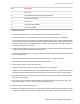
Test Area Enclosure Installation Item Description 7 Foot mount 8 M5 X 35MM socket head screw, M5 butt fastener 9 M5 C'Bore butt fastener 10 Foot mount 11 Right side panel assembly 12 Front door assembly 1. Raise the crosshead. 2. Put two foot mounts (items 7 and 10) on the frame in the provided machined indents. 3. Put a M6 x 1.00 mm x 12mm buttonhead cap screw (item 4) for the top bracket on the baseplate.
Test Area Enclosure Installation 14. It makes installation easier to route and secure the safety switch sensor cable prior to mounting the side panel. a) Place loop clamps over the sensor cable and position the clamps near the provided threaded mounting holes. b) If the safety switch is not pre-mounted, position the safety switch with the cable in a downward direction, and the arrow-on switch pointing forward. Align the safety switch parallel and centered vertically.
Test Area Enclosure Installation g) Loop the cable down and back. Plug it into the enclosure switch connector. In most cases where the test area enclosure is installed after frame installation, it will be necessary to remove a jumper plug first. Do not discard the jumper plug. Keep the jumper plug in case the test area enclosure is removed in the future. The machine requires either the jumper plug or the test area enclosure to function. 15.
Test Area Enclosure Installation 20. Align the front door latch. a) Loosen the top and bottom M4 flathead screws located inside the door latch vertical edge. b) Adjust the latch so that the upper and lower catch ball bearings touch the latch simultaneously. You can view this from the side. c) Slightly tighten the two screws loosened in step 20a such that the latch is somewhat secure.
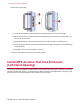
Test Area Enclosure Installation Test Area Enclosure Item Description 1 Rear panel assembly 2 M6 x 1 mm x 35 mm socket low head screw 3 Top bracket 4 M6 x 1.00 mm x 12 mm buttonhead cap screw 5 M6 x 25MM x 12 mm flathead screw 6 Left side panel assembly 7 Foot mount 8 M5 X 35MM socket head screw, M5 butt fastener 9 M5 C'Bore butt fastener 10 Foot mount 11 Right side panel assembly 12 Front door assembly 1. Raise the crosshead. 2.
Test Area Enclosure Installation 4. Put M5 C'Bore butt fasteners (item 9) in the two bottom slots in the side panel and insert the DIN912 M5 x 0.80 mm x 30 mm SST sockethead cap screws (item 8). 5. Position the side panel (item 6) on the frame such that the bottom screws fit through the foot mounts and into the threaded holes. 6. Take the screw from step 3 and secure the top bracket (item 3) to the frame. Hand-tighten. 7. Hand-tighten the screws securing the side panel to the frame base. 8.
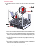
Test Area Enclosure Installation 20. Route and secure the safety switch sensor cable.
Test Area Enclosure Installation a) Place the loop clamps onto the sensor cable, and position the clamps near the provided threaded mounting holes on the vertical side edge and bottom left cross edge. b) Position the safety switch with the cable in an upward direction and the arrow-on switch pointing forward. Align the safety switch parallel and centered to vertical edge. Using the M4 x 25mm lg socket head cap screw and M4 washer, mount the switch to the side panel and torque to 0.57 N-m (5 lb-in.
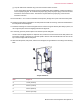
Test Area Enclosure Installation Torque Guidelines Item Torque to A 11 N-m (8.2 lb-ft) B 10 N-m (7.3 lb-ft) C 12 N-m (8.8 lb-ft) D 6.5 N-m (4.8 lb-ft) 26. Align the front door latch.
Test Area Enclosure Installation a) Loosen the top and bottom M4 flathead screws located inside the door latch vertical edge. b) Adjust the latch so that the upper and lower catch ball bearings touch the latch simultaneously. You can view this from the side. c) Slightly tighten the two screws loosened in step 20a such that the latch is somewhat secure. d) Close and open the door two or three times to allow the latch to align exactly with the catch ball bearings on the side panel.
100-265-243 A