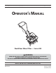
Safe Operation Practices • Set-Up • Operation • Maintenance • Service • Troubleshooting • Warranty Operator’s Manual World Rear Wheel Tiller — Series 200 WARNING READ AND FOLLOW ALL SAFETY RULES AND INSTRUCTIONS IN THIS MANUAL BEFORE ATTEMPTING TO OPERATE THIS MACHINE. FAILURE TO COMPLY WITH THESE INSTRUCTIONS MAY RESULT IN PERSONAL INJURY. MTD LLC, P.O. BOX 361131 CLEVELAND, OHIO 44136-0019 Printed In USA Form No.
1 To The Owner Thank You Thank you for purchasing an MTD Garden Tiller. It was carefully engineered to provide excellent performance when properly operated and maintained. Please read this entire manual prior to operating the equipment. It instructs you how to safely and easily set up, operate and maintain your machine. Please be sure that you, and any other persons who will operate the machine, carefully follow the recommended safety practices at all times.
2 Important Safe Operation Practices WARNING! This symbol points out important safety instructions which, if not followed, could endanger the personal safety and/or property of yourself and others. Read and follow all instructions in this manual before attempting to operate this machine. Failure to comply with these instructions may result in personal injury. When you see this symbol.
c. When practical, remove gas-powered equipment from the truck or trailer and refuel it on the ground. If this is not possible, then refuel such equipment on a trailer with a portable container, rather than from a gasoline dispenser nozzle. d. Keep the nozzle in contact with the rim of the fuel tank or container opening at all times until fueling is complete. Do not use a nozzle lock-open device. e. Extinguish all cigarettes, cigars, pipes and other sources of ignition.
9. If the fuel tank has to be drained, do this outdoors. 10. Observe proper disposal laws and regulations for gas, oil, etc. to protect the environment. 11. According to the Consumer Products Safety Commission (CPSC) and the U.S. Environmental Protection Agency (EPA), this product has an Average Useful Life of seven (7) years, or 130 hours of operation.
Safety Symbols This page depicts and describes safety symbols that may appear on this product. Read, understand, and follow all instructions on the machine before attempting to assemble and operate. Symbol Description READ THE OPERATOR’S MANUAL(S) Read, understand, and follow all instructions in the manual(s) before attempting to assemble and operate WARNING— ROTATING TINES Do not put hands or feet near rotating parts. Contact with the rotating parts can amputate hands and feet.
3 Assembly & Set-Up Contents of Carton • One Tiller • • One Engine Operator’s Manual One 20 oz. bottle of oil NOTE: Stand behind the tiller as if you were going to operate it. Your right hand corresponds to the right side of the tiller and your left hand corresponds to the left side of the tiller. 2. NOTE: This operator’s manual may cover various models of tillers. The machines illustrated may vary slightly from your tiller.
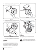
4. Insert the left end of the tine clutch control into the hole on the left side of the upper handle. See Fig. 3-3. Clutch Control Tine Clutch Control Figure 3-5 Figure 3-3 5. Insert the Z-fitting on the clutch cable into the hole on the tine clutch control. Hook the “Z” end into the opening from the inside to the outside as shown in Fig. 3-4. Cotter Pin Clevis Pin Z-fitting Clutch Cable Tine Clutch Control Figure 3-4 6. Squeeze the tine clutch control inward.
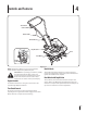
4 Controls and Features Tine Clutch Control Clutch Cable Handle Knobs Depth Stake Tines Rear Wheel Rear Wheel Depth Stake Figure 4-1 NOTE: This Operator’s Manual covers several garden tiller models. The tiller depicted may differ from yours. WARNING! Before operating your machine, carefully read and understand all safety, controls and operating instructions in this manual and on the decals on the machine. Failure to follow these instructions can result in serious personal injury.
5 Operation WARNING! Read, understand, and follow all instructions and warnings posted on the machine, in this manual and in the seperate engine manual before operating. WARNING! Be sure no one other than the operator is standing near the tiller while starting the engine or operating the unit. Never run the engine indoors or in enclosed, poorly ventilated areas. Engine exhaust contains carbon monoxide, an odorless and deadly gas.
In some soils, the desired depth is obtained the first time over the garden. In other soils, the desired depth is obtained by going over the garden two or three times. Passes should be made across the length and width of the garden alternately. Rocks which are turned up should be removed from the garden area. Handle Pressure Further control of tilling depth and travel speed can be obtained by variation of pressure on the handles.
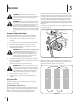
6 Maintenance & Adjustments warning! Before inspecting, cleaning or servicing the tiller, shut off the engine and wait for all moving parts to come to a complete stop. Disconnect the spark plug. Failure to follow these instructions properly can result in serious personal injury or property damage. Depth Stake The depth stake acts as a brake for the tiller and controls the depth and speed at which the machine will operate, Figure 6-2.
7 Service Belt Replacement 2. Loosen the lock nut shown in Fig. 7-2. Your tiller has been engineered with a belt made of special material for longer life and better performance. Replace with a factory-approved OEM belt. See the retailer from which you purchased your tiller, an authorized MTD Service Dealer, or call 1-800-800-7310 for information regarding price and availability. 1.
8 Troubleshooting Problem Engine Fails to start Engine runs erratic Engine overheats Tines do not engage Cause Remedy 1. Spark plug wire disconnected 1. Connect wire to spark plug 2. Fuel tank empty or stale fuel 2. Fill tank with clean, fresh gasoline 3. Throttle control lever (if equipped) not in correct starting position 3. Move throttle lever to start position 4. Choke not in ON position 4. Move lever to ON position 5. Blocked fuel line 5. Clean fuel line 6. Faulty spark plug 6.
9 Replacement Parts Component Part Number and Description 642-0002 642-0003 Inner Right Hand Tine (Series 240) Inner Leftt Hand Tine (Series 240) 642-0005 642-0004 Outer Left Hand Tine (Series 240) Outer Right Hand Tine (Series 240) 714-04043 711-0415 Bow-tie Pin Clevis Pin 642-04032 Right Hand Tine Assembly (Series 220) 642-04031 Left Hand Tine Assembly (Series 220) 946-04626 Clutch Cable 734-0973 Wheels, 5” x 1.
MANUFACTURER’S LIMITED WARRANTY FOR The limited warranty set forth below is given by MTD LLC with respect to new merchandise purchased and used in the United States and/or its territories and possessions, and by MTD Products Limited with respect to new merchandise purchased and used in Canada and/ or its territories and possessions (either entity respectively, “MTD”).