
Operator`s manual


7
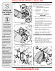
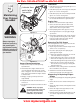
Fgure 3-5
3
Figure 3-6
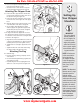
Figure 3-7
b. Place second spacer over hex bolt inside other
hinge and secure with hex lock nut.
c. Secure both sides of chute deflector to impeller
housing using wing knobs previously removed.
Attaching The Chipper Chute
5. a. Remove the three cupped washers and hex nuts
from weld studs around the opening on the side of
the impeller housing. See Figure 3-5.
b. Remove the hex bolts, flat washers, and lock nuts
from the two holes on the upper end of the support
brace.
6. a. Align the chipper chute over the weld studs, so the
slot in the bottom of the chute is facing down.
b. Secure chipper chute with the three cupped
washers (cupped side against the chipper chute)
and hex nuts previously removed. Do not tighten
the nuts at this time. See Figure 3-6.
7. The chipper shredder was shipped with one end of
the support brace already secured to the lower frame.
Loosen but do not remove the bolts securing the brace
to the frame. See Figure 3-7.
a. Align the holes in the chute with the holes in the top
of the brace and attach brace to chipper chute with
hardware previously removed. Tighten securely.
b. Tighten the bolts securing the support brace to the
frame.
c. Tighten the three nuts on the weld studs holding
the chipper chute to the impeller housing.
Attaching The Bag
8. To attach the bag:
a. Place the opening of the bag completely over the
chute deflector.
b. Pull on the drawstring until the bag is tight around
chute deflector opening.
c. Clip drawstring back on itself, tight against chute
deflector to secure into position. See Figure 3-8.
Figure 3-8
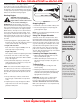
Setting Up
Your Chipper
Shredder
!
"
#
!
"
!
"
#
!
"
NOTE: All references
in this manual to the
left or right side of
the chipper shredder
is from the operating
position only. Excep-
tions, if any, will be
specified.
IMPORTANT
This unit is shipped
without gasoline or
oil in the engine. Be
certain to service
engine with gasoline
and oil as instructed
in the separate engine
manual before operat-
ing your machine.
NOTE: This Operators
Manual covers a range
of product specifica-
tions for various
models. Characteristics
and features discussed
and/or illustrated in this
manual may not be ap-
plicable to all models.
MTD LLC reserves the
right to change product
specifications, designs
and equipment without
notice and without
incurring obligation.
For Parts Call 606-678-9623 or 606-561-4983
www.mymowerparts.com
For Parts Call 606-678-9623 or 606-561-4983
www.mymowerparts.com