OPERATOR’S MANUAL Model Numbers E602E,E642E, E642F, E662E, E662H, 614E, E644E, E664F, E6A4E Model Style 4 Shown IMPORTANT: READ SAFETY RULES AND INSTRUCTIONS CAREFULLY Warning: This unit is equipped with an internal combustion engine and should not be used on or near any unimproved forestcovered, brush-covered or grass-covered land unless the engine’s exhaust system is equipped with a spark arrester meeting applicable local or state laws (if any).
SECTION 1: FINDING YOUR MODEL NUMBER This Operator’s Manual is an important part of your new snow thrower. It will help you assemble, prepare and maintain your snow thrower. Please read and understand what it says. Before you start to prepare your snow thrower for its first use, please locate the model plate and copy the information from it in this Operator’s Manual. The information on the model plate is very important if you need help from your dealer or the MTD customer support department.
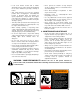
SECTION 3: IMPORTANT SAFE OPERATION PRACTICES WARNING: THIS SYMBOL POINTS OUT IMPORTANT SAFETY INSTRUCTIONS WHICH, IF NOT FOLLOWED, COULD ENDANGER THE PERSONAL SAFETY AND/OR PROPERTY OF YOURSELF AND OTHERS. READ AND FOLLOW ALL INSTRUCTIONS IN THIS MANUAL BEFORE ATTEMPTING TO OPERATE YOUR SNOW THROWER. FAILURE TO COMPLY WITH THESE INSTRUCTIONS MAY RESULT IN PERSONAL INJURY. WHEN YOU SEE THIS SYMBOL-HEED ITS WARNING.
• If the snow thrower should start to vibrate abnormally, stop the engine and check immediately for the cause. Vibration is generally a warning of trouble. • Never operate the machine at high transport speeds on slippery surfaces. Look behind and use care when backing. • Never direct discharge at bystanders or allow anyone in front of unit.
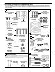
SECTION 4: CONTENTS OF HARDWARE PACK Lay out the hardware according to the illustration for identification purposes. Parts are illustrated approximately one-half size. Part numbers are shown in parentheses. (Hardware pack may contain extra items which are not used on your unit.
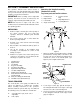
SECTION 5: ASSEMBLY INSTRUCTIONS This operator’s manual covers various models of snow throwers. The units illustrated may vary slightly from your unit. Follow only those instructions which pertain to your model snow thrower. Attaching the Handle Assembly. (Hardware A and E) Lay loose parts out on flat surface. IMPORTANT: After assembly, service engine with 1. Handle Panel gasoline, and check oil level as instructed in the separate engine manual packed with your unit. 2. Right Handle 5.
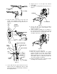
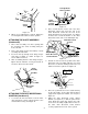
6. Repeat process for the right side Traction Control Grip. 7. Lay handle assembly behind snow thrower. See Figure 7. Triangle Metal Tab Auger Control Grip “Z” Fitting Hex Bolt Figure 5 4. Place the auger control grip on top of the left handle. The triangular metal tab must be between the handle and the grip bracket. See Figure 6. Lock Washer Triangle Metal Tab Figure 7 8. Insert a hex bolt 3/4” long and lock washer through the lower hole on the bottom of the handle. See Figure 7. 9.
Flat Washer Lock Washers Cable Roller Hex Bolt Guide Handle 3/4” Long Tab Hex Bolt 1-3/4” Long Ferrule Shift Rod Flat Washer Figure 9 Hairpin Clip ATTACHING SHIFT ROD (Hardware D) Figure 11 3. Models 602, 642, 662: Thread the ferrule up or down the shift rod and align with the lower hole on the shift lever assembly behind the handle panel. See Figure 10 .
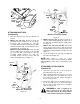
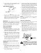
Carriage Bolts Hex Lock Nuts “Z” Hex Nut Chute Directional Control Bracket Cable is Straight Figure 14 2. Place one flat washer over the end of the chute directional control, then insert the end of the chute directional control into the hole in the plastic bushing in the chute bracket. See Figure 15. Place the second flat washer on the chute directional control, and secure with hairpin clip. Figure 12 4. When correct adjustment is reached, tighten the hex nut against the cable to lock it in position.
6. Check to make sure all nuts and bolts on the control panel and all four bolts which secure the handles to the frame are tight. LAMP WIRING (If Equipped) Lamp Wire Alternator Lead Right Handle Figure 17 1. Wrap the wire from the lamp down the right handle until the wire can be plugged into the alternator lead wire under the fuel tank. See Figure 17. Be sure lamp wire does not interfere with the movement of any controls or cables.
SECTION 6: CONTROLS THROTTLE CONTROL TRACTION CONTROL CLUTCH The throttle control is located on the engine. It regulates the speed of the engine. See Figure 20. (See Figure 21 for Model 602, 642 and 662. See Figure 22 for Models 614, 644, 664, and 6A4) The traction control clutch is located on the right handle. Squeeze the traction control clutch to engage the wheel drive. Release to stop. SAFETY IGNITION SWITCH The ignition key must be inserted in the switch before the unit will start.
SECTION 7: OPERATION BEFORE STARTING WARNING: Observe all Warning Labels ENGINE WILL NOT START UNLESS IGNITION KEY IS INSERTED INTO IGNITION SLOT IN CARBURETOR COVER. DO NOT TURN IGNITION KEY. on the snow thrower prior to use. See Figure 2. Your snow thrower is shipped with oil; however, you must check the oil level before operating. Be careful not to overfill. Electric Starter: (If Equipped) WARNING: The electric starter is The spark plug wire was disconnected for safety.
Recoil Starter: 6. When engine starts, release starter button, and move choke gradually to OFF. If engine falters, move choke immediately to FULL and then gradually to OFF. With engine running, pull starter rope with a rapid, continuous full arm stroke three or four times. Pulling the starter rope will produce a loud clattering sound, which is not harmful to the engine or starter. 7. Repeat steps 6 and 7 until engine starts. If engine fails to start, repeat steps 5, 6, and 7 until engine starts. 3.
• Set the skid shoes 1/4" below the scraper bar for normal usage. The skid shoes may be adjusted upward for hard-packed snow. Adjust downward when using on gravel or crushed rock. • Be certain to follow the precautions listed under ‘‘To Stop Engine’’ in previous column to prevent possible freeze-up. • Clean the snow thrower thoroughly after each use. SECTION 8: ADJUSTMENTS WARNING: Never attempt to clean chute or make any adjustments while engine is running. 2.
ADJUSTING SHIFT ROD Minor carburetor adjustment may be required to compensate for differences in fuel, temperature, altitude and load. Refer to the separate engine manual packed with your unit for carburetor adjustment information. 1. Remove the hairpin clip and flat washer from the ferrule and remove the ferrule from the shift lever. Place the shift lever in the fastest forward speed position. Models 602, 642, 662: DRIVE WHEELS 2. Push up on the shift arm assembly as far as it will go.
To remove skid shoes, remove the four carriage bolts, belleville washers and hex nuts which attach them to the snow thrower. Reassemble new skid shoes with the four carriage bolts, belleville washers (cupped side goes against skid shoes) and hex nuts. Make certain the skid shoes are adjusted to the same level on both sides. To remove shave plate, remove the carriage bolts, belleville washers and hex nuts which attach it to the snow thrower housing.
Drive Belt Rear Auger Belt Friction Wheel Engine Pulley Front Auger Belt Idler Pulley Support Bracket Engine Pulley Idler Pulley Frame Rear Auger Belt Figure 29 NOTE: It may be necessary to loosen the six hex Front Auger Pulley nuts that fasten the frame to the auger housing to aid in belt removal. 5. Roll the front and rear auger belts off the engine pulley. See Figure 29. Support Auger Idler Auger Bracket Pulley Spring Housing Spring Figure 30 6.
5. Using a 7/8" wrench to hold the shaft, loosen, but do not completely remove, the hex nut and bell washer on the left end of gear shaft. See Figure 32. 6. Lightly tap the hex nut to dislodge the ball bearing from the right side of frame. Remove the hex nut and bell washer from left end of shaft. 7. Slide the gear shaft to the right and slide the friction wheel assembly from the shaft. 8. Remove the six screws from the friction wheel assembly (three from each side).
SECTION 12: TROUBLE SHOOTING GUIDE Trouble Possible Cause(s) Corrective Action Engine fails to start Fuel tank empty, or stale fuel. Fill tank with clean, fresh gasoline. Fuel will not last over thirty days unless a fuel stabilizer is used. Blocked fuel line. Clean fuel line. Choke not in ON position Move switch to ON position Faulty spark plug. Clean, adjust gap or replace. Key not in switch on engine. Insert key. Spark plug wire Connect spark plug wire. disconnected. Primer button not depressed.
Blower Housing E602E, E642E, E642F, E662E, E662H, 614E, E644E, E664F AND E6A4E 8 7 6 9 5 10 38 11 3 12 9 2 1 4 14 21 13 7 6 16 20 8 15 18 29 30 31 32 7 34 13 19 18 22 23 37 26 33 24 13 33 6 28 36 16 27 37 32 6 7 33 25 33 31 32 30 6 35 36 20 32 17 16
Blower Housing E602E, E642E, E642F, E662E, E662H, 614E, E644E, E664F AND E6A4E REF. NO. 1 2 3 4 5 6 7 8 9 10 11 12 13 14 15 16 17 18 19 20 21 22 23 24 PART NO. 712-0116 756-0178 784-5632A 710-0459A 741-0475 736-0242 712-3010 712-0324 736-0463 705-5226 731-1379A 710-0703 710-0451 738-0281 736-0174 712-3068 732-0611 736-0119 05931 741-0309 684-0039C 684-0040C 684-0041C 684-0055B 736-0169 712-0798 784-5580 DESCRIPTION Lock Jam Nut 3/8-24 Flat Idler Auger Idler Arm Hex Cap Screw 3/8-24 x 1.
Handle Assembly E602E, E642E, E642F, E662E, E662H, 614E, E644E, E664F AND E6A4E 17 16 18 17 20 2 1 8 16 3 4 5 19 22 27 26 20 6 25 18 23 9 19 28 24 7 11 10 21 12 29 13 30 38 39 22 15 24 24 6 53 40 14 7 41 39 34 23 42 35 7 43 23 37 36 44 29 47 45 46 51 50 48 49 52 22
Handle Assembly E602E, E642E, E642F, E662E, E662H, 614E, E644E, E664F AND E6A4E REF. NO. 1 2 3 4 5 6 7 8 9 10 11 12 13 14 15 16 17 18 19 20 21 22 23 24 25 PART NO. 712-0116 732-0193 736-0105 784-5619A 710-0459A 736-0275 714-0104 720-0232 711-0677 726-0100 747-0921 720-0201A 705-5204A 747-0697 735-0234 684-0008A 720-0274 705-5233 705-5234 750-1032 735-0199A 746-0778 705-5275 712-0429 736-0119 712-3010 705-5274 REF. NO.
Frame Assembly E602E, E642E, E642F, E662E, E662H, 614E, E644E, E664F AND E6A4E 27 20 37 39 Drive Clutch Cable 20 5 13 7 38 1 11 6 10 37 Auger Clutch Cable 4 3 40 4 1 2 14 15 26 5 36 16 16” Wheels 25 13” or 15” Wheels 7 31 28 23 10 12 17 21 18 32 9 11 25 24 8 4 1 22 33 1 20 29 8 5 34 19 26 35 Blower Housing 30 1 24 1 Auger Clutch Cable
Frame Assembly E602E, E642E, E642F, E662E, E662H, 614E, E644E, E664F AND E6A4E REF. NO. 1 2 3 4 5 6 7 8 9 10 11 12 13 14 15 16 17 18 19 20 21 PART NO. 710-1652 784-5688 784-5687A 756-0625 738-0924 684-0030 741-0563 736-0105 712-0116 741-0598 736-0188 784-5689A 710-0538 736-0242 714-0474 736-0160 710-0788 784-5590 784-5638 710-0599 736-0351 REF. NO.
Engine and V-Belts IMPORTANT: For a proper working machine, use Factory Approved Parts. V-BELTS are specially designed to engage and disengage safely. A substitute (non OEM) V-Belt can be dangerous by not disengaging completely. E602E, 614E 1 2 3 5 4 8 9 11 13 10 12 27 15 16 20 22 4 16 7 6 23 14 24 18 17 19 25 REF. NO. 1 2 3 4 5 6 7 8 9 10 11 12 13 14 PART NO.
Engine and V-Belts E642E, E642F, E662E, E662H, 614E, E644E, E664F AND E6A4E 1 2 26 4 3 5 9 8 10 21 20 12 11 20 21 5 20 7 6 22 23 14 13 24 16 25 18 19 REF. NO. 1 2 3 4 5 6 7 8 9 10 11 12 13 PART NO. 710-1652 731-1324 710-3005 732-0710 710-0627 05896A 748-0234 756-0987 754-0346 756-0986 736-0270 710-0230 756-0313 IMPORTANT: For a proper working machine, use Factory Approved Parts. V-BELTS are specially designed to engage and disengage safely.
MANUFACTURER’S LIMITED WARRANTY FOR: The limited warranty set forth below is given by MTD PRODUCTS INC (“MTD”) with respect to new merchandise purchased and used in the United States, its possessions and territories. MTD warrants this product against defects in material and workmanship for a period of two (2) years commencing on the date of original purchase and will, at its option, repair or replace, free of charge, any part found to be defective in material or workmanship.