
Operation Manual

User manual English
7
free” battery requires maintenance
if it is to have a longer service life.
Keep the battery clean
Avoid tipping the battery.
Electrolyte fluid leaks from a
‘sealed’ battery, if it is tipped.
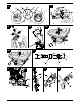
If an empty battery (type 2)
is supplied
(Battery with filler plugs)
Fig. 25
Remove the filler plugs of the
battery cells.
Fill each cell slowly with battery
acid up to 1 cm below the filling
opening.
Leave the battery to stand for
30 minutes so that the lead can
soak up the battery acid.
Check the level of the battery
acid, add more if necessary.
Before using the battery for the
first time, charge it using a battery
charger (max. charging current
12 Volt / 6 Ampere) for 2 to 6
hours. After charging the battery,
first unplug the charger and then
disconnect the battery (see also
the operating instructions for the
battery charger).
Re-insert the filler plugs of the
battery cells.
Install the battery in the unit.
Remove the strip seal from the
battery vent. Connect the venting
hose so that the free end points
downwards in the appliance.
The hose must always allow free
passage! (Fig. 25b)
First connect the red cable (+),
and then the black cable (–).
Thereafter, use only distilled water
to top up the battery (check every
2 months).
Keep the battery clean
=t~êåáåÖ
lÄëÉêîÉ=íÜÉ=çêÇÉê=áå=ïÜáÅÜ=íÜÉ=
Ä~ííÉêó=áë=ãçìåíÉÇ=ïÜÉå=
ÅçååÉÅíáåÖLÇáëÅçååÉÅíáåÖ=íÜÉ=
íÉêãáå~äëK
Fitting:
First connect the red cable
(+ /positive pole) and then the
black cable (– / negative pole).
Removal:
First disconnect the black cable
(– / negative pole) and then the
red cable (+ / positive pole).
Servicing the battery
(type 1/2)
Before leaving the unit idle for a
longer period, it is advisable to
remove the battery and charge it.
The battery should be charged every
2 months during the idle period (off
season), and also before re-
commissioning the unit at start of
season (consult a specialist garage
for further information).
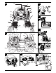
Setting the rollbars upright
Fig. 24
The rollbar is folded down for
transportation.
Remove the linch pins (a) from the
securing pins (b).
Take out the securing pins and
set the rollbar upright.
Place the securing pins through
the drilled holes and secure them
with the linch pins.
Tighten the screw (c) and secure
the screw with the nut (d).
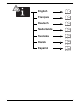
Controls and indicators
t~êåáåÖK=a~ã~ÖÉ=íç=íÜÉ=
~ééäá~åÅÉK
qÜÉ=Åçåíêçä=~åÇ=áåÇáÅ~íçê=ÑìåÅíáçåë=
ïáää=ÄÉ=ÇÉëÅêáÄÉÇ=íç=ÄÉÖáå=ïáíÜK=
aç åçí= éÉêÑçêã=~åó= ÑìåÅíáçåë=~í=íÜáë=
ëí~ÖÉ>
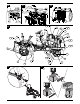
Fig. 1
1 Vehicle illumination switch
2PTO-switch
3Throttle
4 Ignition lock
5 Brake pedal
6 Forward pedal/Reverse pedal
7 Differential lock pedal
8 Parking brake
9 Indicator switch
10 Warning indicator switch
11 Pilot light indicator/Warning
indicator – trailer
12 Horn
13 Pilot lights indicator/Warning
indicator
14 Instrument panel
Fig. 2
15 Tank stopper
16 PTO-switch for reverse driving
17 PTO selector lever
18 Central hydraulics lever
19 Gear lever
20 Can holder
21 Handle bars
22 Indicator/Brake lights
23 Holder symbol
24 Storage area
25 12 V connection socket for
operating trailer
26 Seat belt
27 Auxiliary hydraulics lever
(optional)
28 Additional parking brake
Note
For reasons of clarity, the rollbar is
not shown.
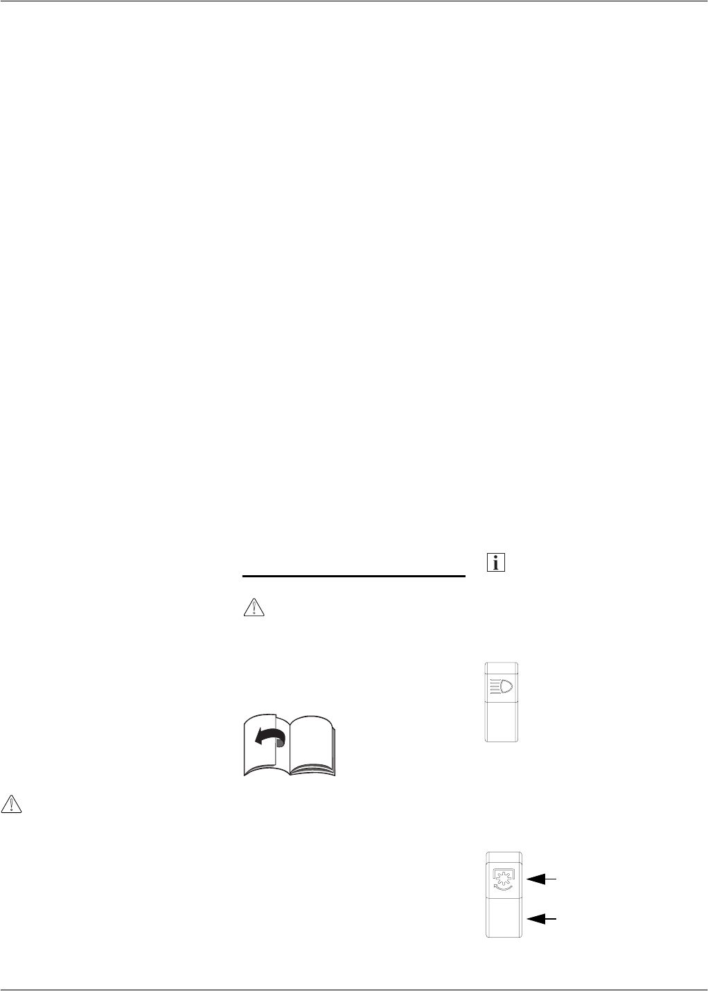
Vehicle illumination switch (1)
Fig. 1
For switching the
headlights and instrument
panel illumination on.
PTO-switch (2)
Fig. 1
Using the PTO switch, the PTO
clutch is switched ON and OFF via
an electro-mechanic coupling.
Engage
Disengage