
Operation Manual

English Operating instructions for lawn tractors
8
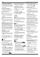
Tank contents display (G)
Fig. 5
As soon as the fuel level has reached
the area of the inspection window (1),
the fuel should be topped up.
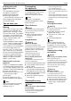
Lever for the gear release
lock (H)
Fig. 6
To push the unit when the engine
is switched off.
Pull out lever and press upwards.
To drive the unit, push lever down
and press in.
The lever is situated on the rear panel
of the machine.
Dipstick/Filler inlet
for gear oil (I)
Fig. 5
For checking the level or adding
gear oil.
Fuel tank/Filler inlet (J)
Fig. 1
Storage bin (K)
Fig. 1
Can holder (L)
Fig. 1
Adjusting lever for seat (M)
Fig. 7
Pull the lever, and adjust the seat.
Steering wheel adjusting
lever (N) (depending
on model)
Fig. 8
This adjusts the position of the stee-
ring wheel.
Press and keep pressed the lever.
Adjusting the steering wheel.
Release the lever. Ensure that the
steering wheel engages correctly.
Brake pedal (O)
Fig. 1
The brake pedal can be used to brake
quickly, to engage and disengage
the locking brake, and to switch OFF
speed control.
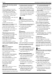
Choke (P/R) (depending
on model)
Fig. 9
To start a cold engine, move the
choke forwards to Position (Fig. 9)
or the throttle to position (Fig. 10).
Throttle (P)
Fig. 10
The engine speed can be adjusted
continuously. Fast engine speed =
. Slow engine speed = .
Switch for parking brake/
Speed control (Q)
Fig. 11
This switch has a dual function:
Actuate the parking brake:
Press brake pedal all the way and pull
switch. Release the brake pedal.
Release the parking brake:
Press down the brake pedal fully,
the switch disengages.
Switching on Tempomat :
When driving, press the switch.
The forward speed selected at this
point (but not top speed) is maintai-
ned, and the drive pedal can be
released.
When the accelerator pedal or the
brake pedal is depressed, the cruise
control automatically switches off.
Note
The Tempomat functions for forward
travel only.
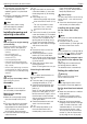
Display cluster (S)
(depending on model)
Fig. 12
According to the model, the combi-
nation indicator can consist of the
following elements.
Oil pressure (1):
The indicator light is lit while the
engine is running, immediately
switch off engine and check oil level.
Where necessary, visit a garage.
Brake (2):
Indicator lamp lights up if the brake
pedal is not depressed or the parking
brake is not locked when the engine
starts.
Cutter deck/Accessories (PTO) (3):
Indicator lamp lights up if the cutter
deck/accessories (PTO) is not
switched off when the engine starts.
Battery charge indicator (4):
If the indicator light lights up when
the engine is running, this means that
the battery is not sufficiently charged.
Where necessary, visit a garage.
Operating hour counter (5):
This function shows the operating
hours as full hours and
1
/
10
of an hour
in the display.
Optional functions:
– When the ignition is switched on,
the battery voltage indicator is indi-
cated for a short period and then
the operating hours are indicated.
The operating hours are always
counted except for when the
ignition key is in the “Stop”
position or when it is removed.
– Each time 50 operating hours have
elapsed (according to the model),
the oil change indicator “CHG/OIL”
appears in the display for five
minutes. This message appears
after the next two hours of opera-
tion. See the engine manual for oil
change intervals.
Steering wheel (T)
Fig. 1
PTO-switch (U)
Fig. 13
The PTO switch switches the cutter
deck/accessories on and off via
an electromechanical clutch.
ON
= pull the switch.
OFF
= press the switch.
Note
When the safety lock system has
automatically switched OFF the appli-
ance (e.g. when reversing with acti-
vated cutters), first switch ON and
then OFF the PTO switch to release
the lock on the clutch.
Light (depending on model)
The headlights are on for as long
as the engine is running or the ignition
key is outside the Stop position .